EasyManuals Logo

YASKAWA Z1000 User Manual

YASKAWA Z1000
400 pages
To Next Page IconTo Next Page
To Previous Page IconTo Previous Page
Page #99 background imageLoading...
Page #99 background image
u
Switches and Jumpers on the Control Board
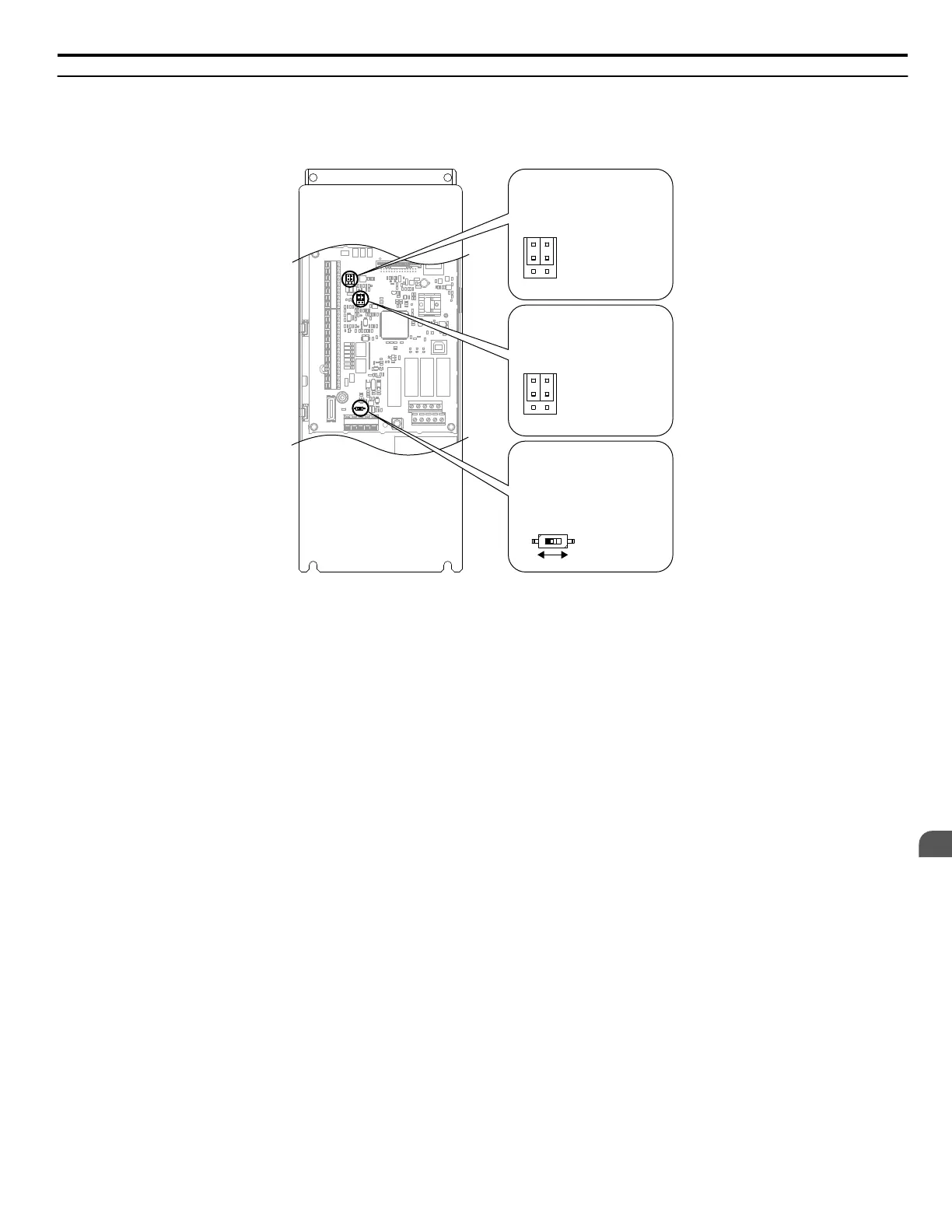
The control board is equipped with several switches used to adapt the drive I/Os to the external control signals. Figure 3.47
shows the location of these switches. Refer to Control I/O Connections on page 100 for setting instructions.
V
I
A1 A2
Jumper S1
Terminal A1/A2
Voltage/Current Selection
OFF
ON
DIP Switch S2
RS-422/RS-485
Termination Resistor
V
I
FM AM
Jumper S5
Terminal FM/AM
Voltage/Current Selection
Figure 3.47 Locations of Jumpers and Switches on the Control Board
3.9 Control Circuit Wiring
YASKAWA ELECTRIC TOEP C710616 45F YASKAWA AC Drive – Z1000 User Manual
99
3
Electrical Installation

Table of Contents

Other manuals for YASKAWA Z1000

Questions and Answers:

Question and Answer IconNeed help?

Do you have a question about the YASKAWA Z1000 and is the answer not in the manual?

YASKAWA Z1000 Specifications

General IconGeneral
ModelZ1000
CategoryController
Humidity95% RH or less (non-condensing)
Control MethodV/F Control
Frequency Range400 Hz
ProtectionOvercurrent, Overvoltage, Undervoltage, Overheat
Communication OptionsModbus
Operating Temperature-10 to 50°C
Storage Temperature-20 to 60°C
AltitudeUp to 1000 meters without derating
Cooling MethodForced Air
Enclosure RatingIP20
Voltage Class200V, 400V

Related product manuals