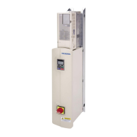
Model
Dimensions mm (in)
Fig. W H W1 W2 H1 H2 H3 H4 H5 H6 H7 H8 H9 H10 H11 A B
2A0143
2A0169
2A0211
2A0273
6
444
(17.48)
824
(32.44)
414
(16.30)
244
(9.61)
156.5
(6.16)
156
(6.14)
156
(6.14)
156
(6.14)
156.5
(6.16)
21.5
(0.85)
24.2
(0.95)
30.8
(1.21)
21.5
(0.85)
– –
385
(15.16)
726
(28.58)
Three-Phase 400 V Class
4A0005
4A0008
4A0011
1
182
(7.17)
383
(15.08)
150
(5.91)
–
62.5
(2.46)
115
(4.53)
115
(4.53)
62.5
(2.46)
– – – – – – –
118
(4.65)
324
(12.76)
4A0014
4A0021
4A0027
2
182
(7.17)
473
(18.62)
150
(5.91)
–
57.5
(2.26)
110
(4.33)
110
(4.33)
110
(4.33)
57.5
(2.26)
– – – – – –
118
(4.65)
414
(16.30)
4A0034
4A0040
3
260
(10.24)
550
(21.65)
230
(9.06)
130
(5.12)
520
(20.47)
150
(5.91)
150
(5.91)
150
(5.91)
– – – – – – –
194
(7.64)
473
(18.62)
4A0052
4A0065
4A0077
4A0096
4
320
(12.60)
585
(23.03)
285
(11.22)
–
555
(21.85)
113
(4.45)
113
(4.45)
113
(4.45)
113
(4.45)
– – – – – –
239
(9.41)
508
(20.00)
4A0124 5
380
(14.96)
746.4
(29.39)
350
(13.78)
170
(6.69)
142.7
(5.62)
140
(5.51)
140
(5.51)
140
(5.51)
142.7
(5.62)
20.5
(0.81)
20.5
(0.81)
21.9
(0.86)
20.5
(0.81)
– –
320
(12.60)
663
(26.10)
4A0156
4A0180
4A0240
6
444
(17.48)
824
(32.44)
414
(16.30)
244
(9.61)
156.5
(6.16)
156
(6.14)
156
(6.14)
156
(6.14)
156.5
(6.16)
21.5
(0.85)
24.2
(0.95)
30.8
(1.21)
21.5
(0.85)
– –
385
(15.16)
726
(28.58)
4A0302 7
556
(21.89)
1083
(42.64)
529
(20.83)
325
(12.80)
144
(5.67)
150
(5.91)
150
(5.91)
150
(5.91)
150
(5.91)
150
(5.91)
144
(5.67)
22.5
(0.89)
28
(1.10)
29
(1.14)
22.5
(0.89)
499
(19.65)
981
(38.62)
u
Installing a Motor Thermal Overload (oL) Relay on the Drive Output
Motor thermal overload relays protect the motor by disconnecting power lines to the motor due to a motor overload condition.
Install a motor thermal overload relay between the drive and motor:
• When operating multiple motors on a single AC drive.
• When using a power line bypass to operate the motor directly from the power line.
It is not necessary to install a motor thermal overload relay when operating a single motor from a single AC drive. The AC
drive has UL recognized electronic motor overload protection built into the drive software.
Note: 1. Disable the motor protection function (L1-01 = 0) when using an external motor thermal overload relay.
2. Create a sequence to produce an external fault (coast to a stop) when triggered.
n
General Precautions when Using Thermal Overload Relays
Consider the following application precautions when using motor thermal overload relays on the output of AC drives to prevent
nuisance trips or overheat of the motor at low speeds:
• Low speed motor operation
• Use of multiple motors on a single AC drive
• Motor cable length
• Nuisance tripping resulting from high AC drive carrier frequency
Low Speed Operation and Motor Thermal oL Relays
Generally, thermal relays are applied on general-purpose motors. When general-purpose motors are driven by AC drives, the
motor current is approximately 5% to 10% greater than if driven by a commercial power supply. In addition, the cooling
capacity of a motor with a shaft-driven fan decreases when operating at low speeds. Even if the load current is within the motor
rated value, motor overheating may occur. A thermal relay cannot effectively protect the motor due to the reduction of cooling
at low speeds. For this reason, apply the UL recognized electronic thermal overload protection function built into the drive
whenever possible.
UL Recognized Electronic Thermal Overload Function of the Drive
Speed-dependent heat characteristics are simulated using data from standard motors and force-ventilated motors. The motor
is protected from overload using this function.
Using a Single Drive to Operate Multiple Motors
Set parameter L1-01 to 0 to disable thermal overload protection for the drive.
Note: The UL recognized electronic thermal overload function cannot be applied when operating multiple motors with a single drive.
6.5 Installing Peripheral Devices
YASKAWA ELECTRIC TOEP C710616 45F YASKAWA AC Drive – Z1000 User Manual
265
6
Peripheral Devices &
Options

 Loading...


