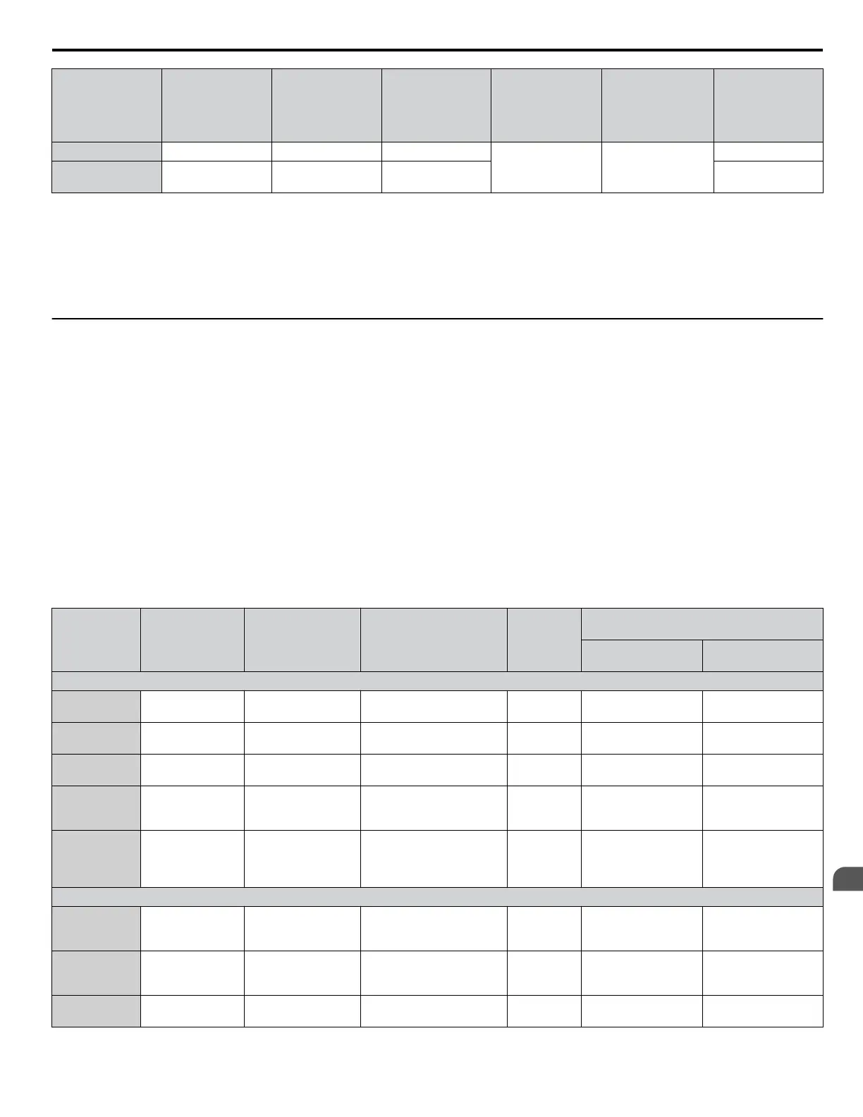
Model
Nominal Output
Power (HP)
AC Drive Input
(A)
MCCB Rating (A)
<1>
Time Delay Fuse
Rating (A)
<2>
Non-time Delay
Fuse Rating (A)
<3>
Bussmann
Semiconductor
Fuse Model
(Fuse Ampere)
<4>
4A0480 400 480 900
<5> <5>
FWH-700A (700)
4A0590 500 590 1100
FWH-1000A
(1000)
<1> Maximum MCCB rating is 15 A, or 200% of drive input current rating, whichever value is larger. MCCB voltage rating must be 600 Vac or greater.
<2> Maximum Time delay fuse is 175% or drive input current rating. This covers any Class J, T, or CC fuse.
<3> Maximum Non-time delay fuse is 300% of drive input current rating. This covers any Class J, T, or CC fuse.
<4> When using semiconductor fuses, Bussmann FWH fuses are required for UL compliance.
<5> Consult factory.
<6> Class L fuse is also approved for this rating.
u
Attachment for External Heatsink Mounting
An external attachment can be used to project the heatsink outside of an enclosure to ensure that there is sufficient air circulation
around the heatsink.
n
IP20 NEMA 1, UL Type 1 Heatsink-External Mounting Attachment
Table 6.4 shows the heatsink-external mounting attachment for an IP20 NEMA 1, UL Type 1 enclosure.
Order parts according to the corresponding product codes in Table 6.4 and install them according to document EZZ021811.
Refer to Table 6.6 for panel cut-out dimensions.
NOTICE: Tighten the installation screws for the bracket and the attachment to the specified tightening torque. Dust can enter if the screw
is loose, and may cause the drive to break down.
NOTICE: If the environment outside the diecast case is relatively harsh, then use either a sealant or a gasket to ensure that the attachment
is firmly affixed. Refer to Table 6.6 for installation details.
NOTICE: The bracket and attachment must match the direction of the installation. Water and dust can enter when the bracket and attachment
are installed incorrectly, and may cause the drive to break down.
Table 6.4 IP20 NEMA 1, UL Type 1 Attachment Code List
Model
Product Code Product Text Parts List
Weight
kg (lb)
Recommended Mounting Hardware
(Not Provided)
Screw Size
Tightening Torque
N·m (lb. in.)
Three-Phase 200 V Class
2A0011
2A0017
100-067-550 72606 -EZZ021811A
Bracket (Qty. 2)
Screw M5x14+S+W (Qty. 8)
0.4 (0.9) Screw M5x14 (Qty. 4)
2.0 to 2.5
(17.7 to 22.1)
2A0024
2A0031
100-067-551 72606 -EZZ021811B
Bracket (Qty. 2)
Screw M5x14+S+W (Qty. 8)
0.6 (1.3) Screw M5x14 (Qty. 4)
2.0 to 2.5
(17.7 to 22.1)
2A0046
2A0059
100-067-552 72606 -EZZ021811C
Bracket (Qty. 2)
Screw M5x14+S+W (Qty. 4)
0.3 (0.7) Screw M6x14 (Qty. 4)
4.0 to 4.9
(35.4 to 43.3)
2A0075
2A0088
2A0114
100-067-553 72606 -EZZ021811D
Bracket (Qty. 2)
Screw M5x14+S+W (Qty. 2)
Screw M6x14+S+W (Qty. 2)
0.4 (0.9) Screw M6x14 (Qty. 4)
4.0 to 4.9
(35.4 to 43.3)
2A0143
2A0169
2A0211
2A0273
– – – – Screw M10x20 (Qty. 4)
17.7 to 22.5
(156.7 to 199.1)
Three-Phase 400 V Class
4A0005
4A0008
4A0011
100-067-550 72606 -EZZ021811A
Bracket (Qty. 2)
Screw M5x14+S+W (Qty. 8)
0.4 (0.9) Screw M5x14 (Qty. 4)
2.0 to 2.5
(17.7 to 22.1)
4A0014
4A0021
4A0027
100-067-551 72606 -EZZ021811B
Bracket (Qty. 2)
Screw M5x14+S+W (Qty. 8)
0.6 (1.3) Screw M5x14 (Qty. 4)
2.0 to 2.5
(17.7 to 22.1)
4A0034
4A0040
100-067-552 72606 -EZZ021811C
Bracket (Qty. 2)
Screw M5x14+S+W (Qty. 4)
0.3 (0.7) Screw M6x14 (Qty. 4)
4.0 to 4.9
(35.4 to 43.3)
6.5 Installing Peripheral Devices
YASKAWA ELECTRIC TOEP C710616 45F YASKAWA AC Drive – Z1000 User Manual
257
6
Peripheral Devices &
Options

 Loading...


