u
Wire Gauges and Tightening Torque
Use the tables in this section to select the appropriate wires and crimp terminals.
Gauges listed in the tables are for use in the United States.
Note: 1. Wire gauge recommendations based on drive continuous current ratings using 75 °C 600 Vac vinyl-sheathed wire assuming ambient
temperature within 40 °C and wiring distance less than 100 m.
2. Terminal +3 is not used. Do not connect devices or wiring to this terminal.
• Consider the amount of voltage drop when selecting wire gauges. Increase the wire gauge when the voltage drop is greater
than 2% of motor rated voltage. Ensure the wire gauge is suitable for the terminal block. Use the following formula to
calculate the amount of voltage drop:
Line drop voltage (V) =
× wire resistance (Ω/km) × wire length (m) × current (A) × 10
-3
• Refer to UL Standards Compliance on page 372 for information on UL compliance.
Yaskawa recommends using closed-loop crimp terminals on all drive models. To maintain UL/cUL approval, UL Listed
closed-loop crimp terminals are specifically required when wiring the drive main circuit terminals on models 2A0031 to
2A0396 and 4A0034 to 4A0590. Use only the tools recommended by the terminal manufacturer for crimping.Refer to Closed-
Loop Crimp Terminal Size on page 372 for closed-loop crimp terminal recommendations.
The wire gauges listed in the following tables are Yaskawa recommendations. Refer to NEC table 310-16 for proper wire
gauge selection for terminals -M, +M, -1, +3, and ground.
n
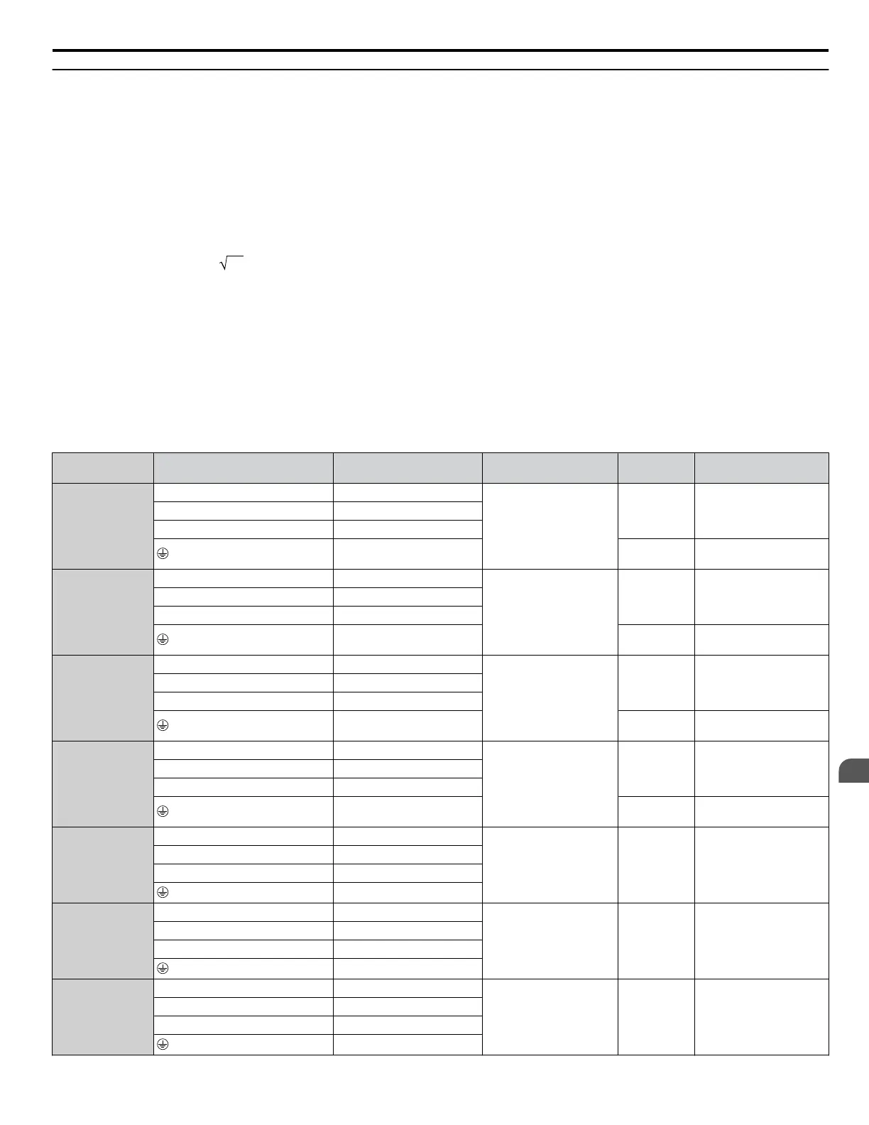
Three-Phase 200 V Class
Table 3.2 Wire Gauge and Torque Specifications (Three-Phase 200 V Class)
Model Terminal
Recomm. Gauge
AWG, kcmil
Wire Range
AWG, kcmil
Screw
Size
Tightening Torque
N·m (lb. in.)
2A0011
R/L1, S/L2, T/L3 14
14 to 8
M4
1.6 to 1.8
(14 to 16)
U/T1, V/T2, W/T3 14
-M, +M –
– M5
2.7 to 3.0
(24 to 27)
2A0017
R/L1, S/L2, T/L3 10
14 to 8
M4
1.6 to 1.8
(14 to 16)
U/T1, V/T2, W/T3 10
-M, +M –
– M5
2.7 to 3.0
(24 to 27)
2A0024
R/L1, S/L2, T/L3 8
14 to 8
M4
1.6 to 1.8
(14 to 16)
U/T1, V/T2, W/T3 8
-M, +M –
– M5
2.7 to 3.0
(24 to 27)
2A0031
<1>
R/L1, S/L2, T/L3 8
14 to 8
M4
1.6 to 1.8
(14 to 16)
U/T1, V/T2, W/T3 8
-M, +M –
– M5
2.7 to 3.0
(24 to 27)
2A0046
<1>
R/L1, S/L2, T/L3 6
10 to 4 M5
2.7 to 3.0
(24 to 27)
U/T1, V/T2, W/T3 6
-M, +M –
–
2A0059
<1>
R/L1, S/L2, T/L3 4
10 to 4 M5
2.7 to 3.0
(24 to 27)
U/T1, V/T2, W/T3 4
-M, +M –
–
2A0075
<1>
R/L1, S/L2, T/L3 3
8 to 2/0 M8
5.4 to 6.0
(48 to 53)
U/T1, V/T2, W/T3 3
-M, +M –
–
3.8 Main Circuit Wiring
YASKAWA ELECTRIC TOEP C710616 45F YASKAWA AC Drive – Z1000 User Manual
83
3
Electrical Installation

 Loading...


