Table 3.14 Parameters H3-01 and H3-09 Details
No. Parameter Name Description
Setting
Range
Default
Setting
H3-01 Terminal A1 signal level selection
Selects the signal level for terminal A1.
0: 0 to 10 V with Zero Limit
1: 0 to 10 V without Zero Limit
2: 4 to 20 mA Current Input
3: 0 to 20 mA Current Input
0 to 3 0
H3-09 Terminal A2 signal level selection
Selects the signal level for terminal A2.
0: 0 to 10 V with Zero Limit
1: 0 to 10 V without Zero Limit
2: 4 to 20 mA Current Input
3: 0 to 20 mA Current Input
0 to 3 0
u
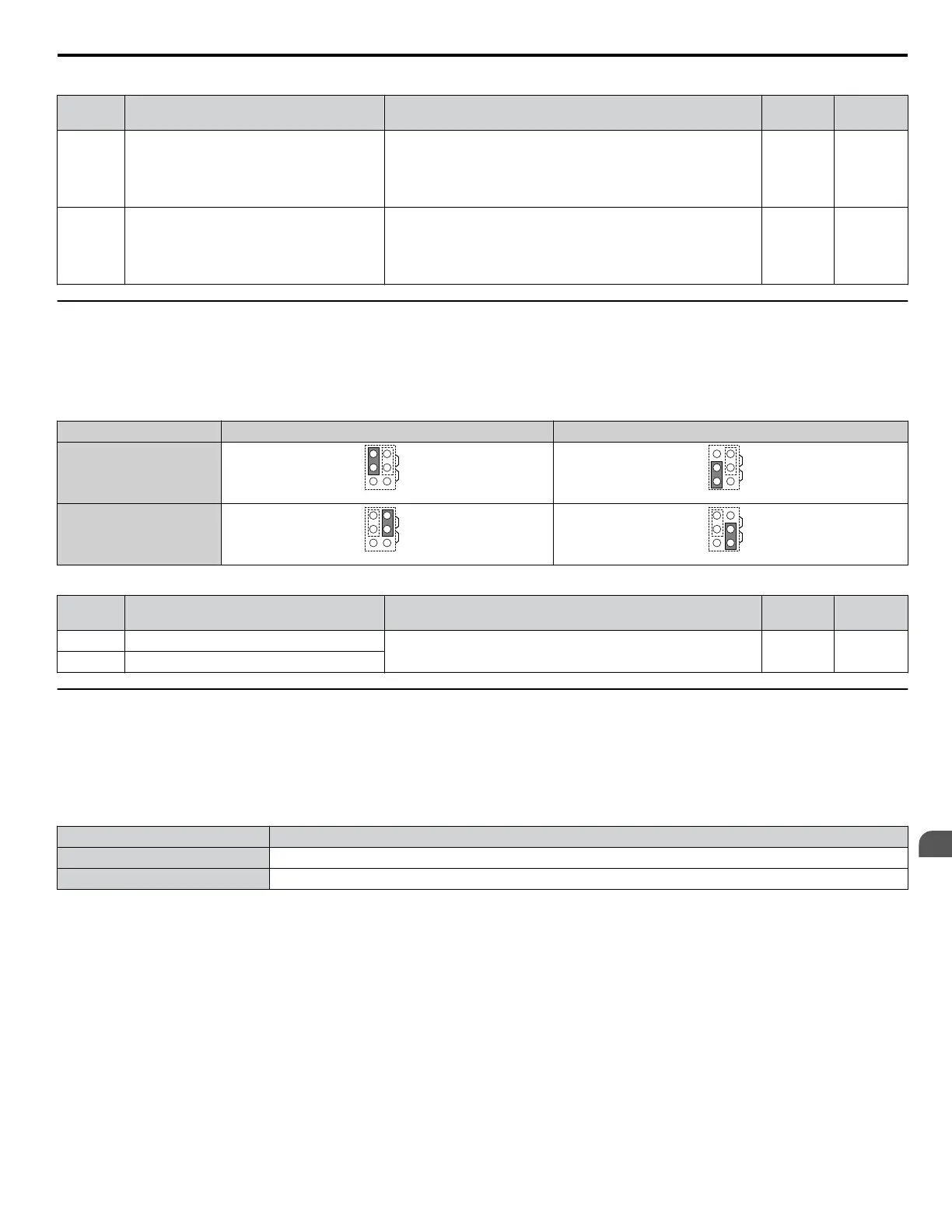
Terminal FM/AM Signal Selection
The signal type for terminals FM and AM can be set to either voltage or current output using jumper S5 on the terminal board
as explained in Table 3.15. When changing the setting of jumper S5, parameters H4-07 and H4-08 must be set accordingly.
The default selection is voltage output for both terminals.
Table 3.15 Jumper S5 Settings
Terminal Voltage Output Current Output
Terminal FM
AMFM
V
I
AMFM
V
I
Terminal AM
AMFM
V
I
AMFM
V
I
Table 3.16 Parameter H4-07 and H4-08 Details
No. Parameter Name Description
Setting
Range
Default
Setting
H4-07 Terminal FM signal level selection
0: 0 to 10 Vdc
2: 4 to 20 mA
0, 2 0
H4-08 Terminal AM signal level selection
u
MEMOBUS/Modbus Termination
This drive is equipped with a built-in termination resistor for the RS-422/RS-485 communication connector. DIP switch S2
enables or disabled the termination resistor as shown in Table 3.17. The OFF position is the default. The termination resistor
should be placed to the ON position when the drive is the last in a series of slave drives. Refer to Switches and Jumpers on
the Control Board on page 99 to locate switch S2.
Table 3.17 MEMOBUS/Modbus Termination Switch S2 Settings
S2 Position Description
ON Internal termination resistor ON
OFF Internal termination resistor OFF (default setting)
3.10 Control I/O Connections
YASKAWA ELECTRIC TOEP C710616 45F YASKAWA AC Drive – Z1000 User Manual
101
3
Electrical Installation

 Loading...


