3.9 Control Circuit Wiring
u
Control Circuit Connection Diagram
Refer to Figure 3.1 on page 63 when wiring terminals on the drive control circuit.
u
Control Circuit Terminal Block Functions
Drive parameters determine which functions apply to the multi-function digital inputs (S1 to S7), multi-function digital outputs
(M1 to M6), multi-function analog inputs (A1 and A2), and multi-function analog monitor output (FM, AM). The default
setting is listed next to each terminal in Figure 3.1 on page 63.
WARNING! Sudden Movement Hazard. Always check the operation and wiring of control circuits after being wired. Operating a drive with
untested control circuits could result in death or serious injury.
WARNING! Sudden Movement Hazard. Confirm the drive I/O signals and external sequence before starting test run. Setting parameter
A1-06 may change the I/O terminal function automatically from the default setting. Failure to comply may result in death or serious injury.
n
Input Terminals
Table 3.7 lists the input terminals on the drive. Text in parenthesis indicates the default setting for each multi-function input.
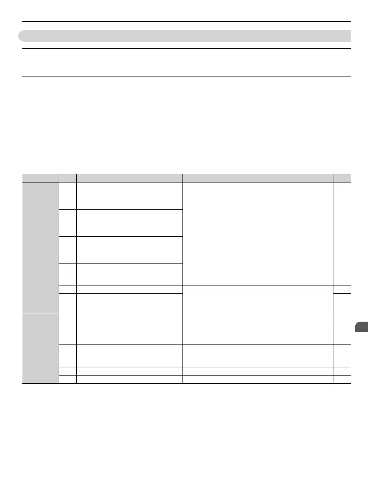
Table 3.7 Control Circuit Input Terminals
Type No. Terminal Name (Function) Function (Signal Level) Default Setting Page
Multi-Function
Digital Inputs
S1
Multi-function input 1
(Closed: Forward run, Open: Stop)
• Photocoupler
• 24 Vdc, 8 mA
• Set the wire jumper to select between sinking, sourcing mode, and
the power supply. Refer to Sinking/Sourcing Mode Switch for
Digital Inputs on page 100.
302
S2
Multi-function input 2
(Closed: Reverse run, Open: Stop)
S3
Multi-function input 3
(External fault, N.O.)
S4
Multi-function input 4
(Fault reset)
S5
Multi-function input 5
(Multi-step speed reference 1)
S6
Multi-function input 6
(Multi-step speed reference 2)
S7
Multi-function input 7
(Jog reference)
SC Multi-function input common Multi-function input common
SP Digital input power supply +24 Vdc 24 Vdc power supply for digital inputs, 150 mA max
NOTICE: Do not jumper or short terminals SP and SN. Failure
to comply will damage the drive.
100
SN Digital input power supply 0 V 100
Frequency
Reference
Inputs
+V Power supply for analog inputs 10.5 Vdc (max allowable current 20 mA) 127
A1
Multi-function analog input 1
(Frequency reference bias)
• 0 to 10 Vdc/100% (input impedance: 20 kΩ)
• 4 to 20 mA/100%, 0 to 20 mA/100% (input impedance: 250 Ω)
• Voltage or current input must be selected by Jumper S1 and H3-01.
127
176
A2
Multi-function analog input 2
(Frequency reference bias)
• 0 to 10 Vdc/100% (input impedance: 20 kΩ)
• 4 to 20 mA/100%, 0 to 20 mA/100% (input impedance: 250 Ω)
• Voltage or current input must be selected by Jumper S1 and H3-09.
127
127
177
AC Frequency reference common 0 V 127
FE Ground for shielded lines and option cards – –
3.9 Control Circuit Wiring
YASKAWA ELECTRIC TOEP C710616 45F YASKAWA AC Drive – Z1000 User Manual
91
3
Electrical Installation

 Loading...


