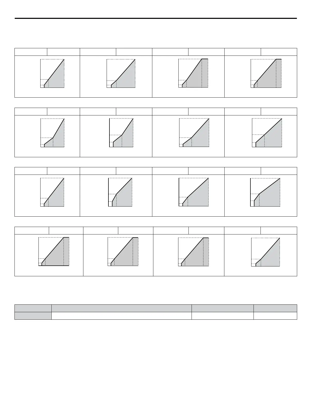
Predefined V/f Patterns for Models 2A0169 to 2A0396 and 4A0096 to 4A0590
The voltage values in the following graphs are specific to 200 V class drives. Double the values for 400 V class drives.
Table 4.34 Rated Torque Characteristics, Settings 0 to 3
Setting = 0 50 Hz Setting = 1 60 Hz Setting = 2 60 Hz Setting = 3 72 Hz
0
6.9
230
1.3 2.5 50
13.8
Voltage (V)
Frequency (Hz)
0
6.9
230
1.5 3 60
13.8
Voltage (V)
Frequency (Hz)
0
6.9
13.8
230
1.5 3 6050
Voltage (V)
Frequency (Hz)
0
6.9
13.8
230
1.5 3 7260
Voltage (V)
Frequency (Hz)
Table 4.35 Variable Torque Characteristics, Settings 4 to 7
Setting = 4 50 Hz Setting = 5 50 Hz Setting = 6 60 Hz Setting = 7 60 Hz
0
5.8
230
1.3 25 50
40.3
Voltage (V)
Frequency (Hz)
0
6.9
230
1.3 25 50
57.5
Voltage (V)
Frequency (Hz)
0
5.8
230
1.5 30 60
40.3
Voltage (V)
Frequency (Hz)
0
6.9
230
1.5 30 60
57.5
Voltage (V)
Frequency (Hz)
Table 4.36 High Starting Torque, Settings 8 to B
Setting = 8 50 Hz Setting = 9 50 Hz Setting = A 60 Hz Setting = B 60 Hz
0
8.1
230
1.3 2.5 50
17.3
Voltage (V)
Frequency (Hz)
0
10.4
230
1.3 2.5 50
23
Voltage (V)
Frequency (Hz)
0
8.1
230
1.5 3 60
17.3
Voltage (V)
Frequency (Hz)
0
12.7
230
1.5 3 60
23
Voltage (V)
Frequency (Hz)
Table 4.37 Constant Output, Settings C to F
Setting = C 90 Hz Setting = D 120 Hz Setting = E 180 Hz Setting = F 60 Hz
0
6.9
13.8
230
1.5 3 9060
Voltage (V)
Frequency (Hz)
0
6.9
13.8
230
1.5 3 12060
Voltage (V)
Frequency (Hz)
0
6.9
13.8
230
1.5 3 18060
Voltage (V)
Frequency (Hz)
0
6.9
230
1.5 30 60
57.5
Voltage (V)
Frequency (Hz)
n
H3-01: Terminal A1 Signal Level Selection
Selects the input signal level for analog input A1. Set jumper S1 on the terminal board accordingly for voltage input or current
input.
No. Name Setting Range Default
H3-01 Terminal A1 Signal Level Selection 0 to 3 0
Setting 0: 0 to 10 V with Zero Limit
The input level is 0 to 10 Vdc with zero limit. The minimum input level is limited to 0%, so that a negative input signal due
to gain and bias settings will be read as 0%.
Setting 1: 0 to 10 V without Zero Limit
The input level is 0 to 10 Vdc without zero limit. If the resulting voltage is negative after being adjusted by gain and bias
settings, then the motor will rotate in reverse.
Setting 2: 4 to 20 mA Current Input
The input level is 4 to 20 mA. Negative input values by negative bias or gain settings are limited to 0%.
4.13 Advanced Drive Setup Adjustments
176
YASKAWA ELECTRIC TOEP C710616 45F YASKAWA AC Drive – Z1000 User Manual

 Loading...


