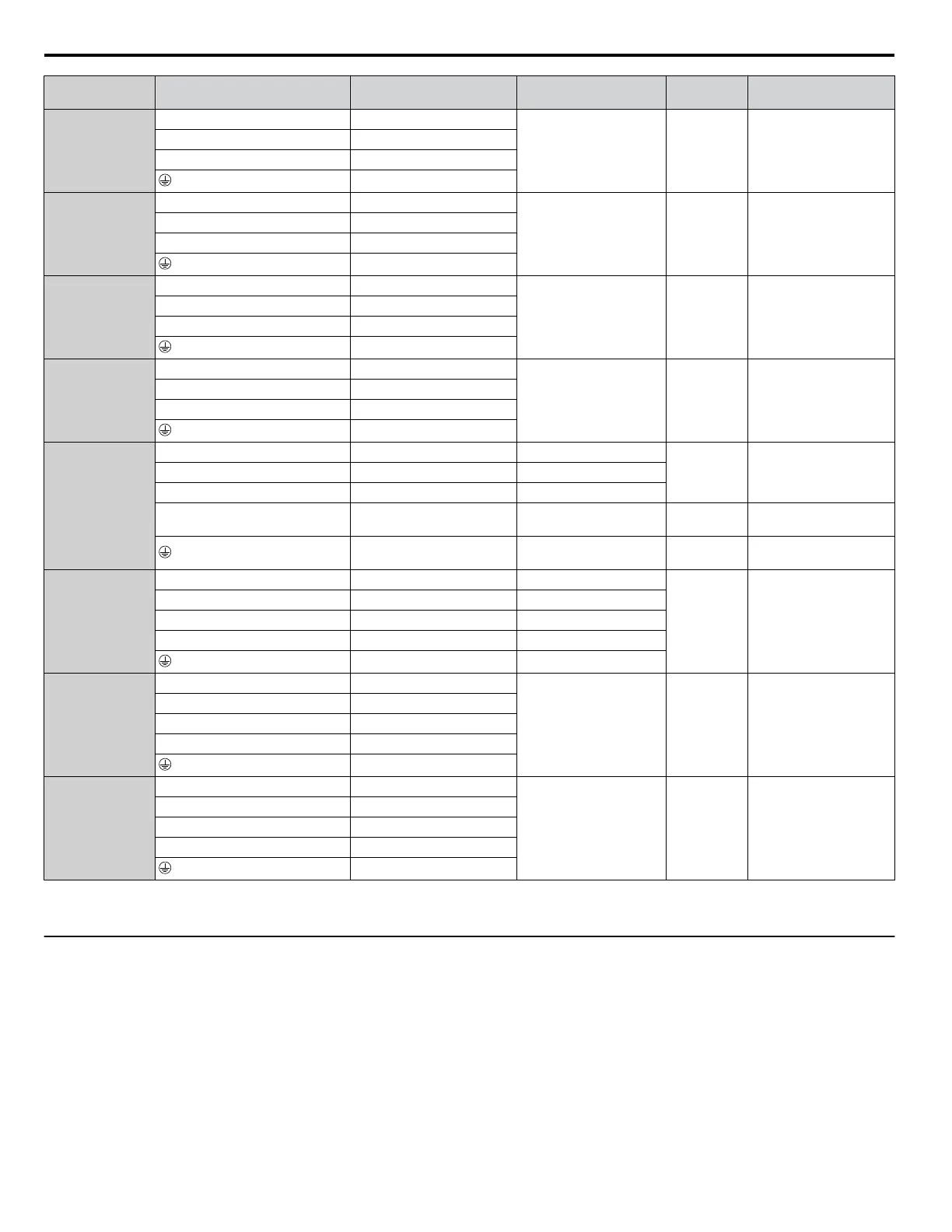
Model Terminal
Recomm. Gauge
AWG, kcmil
Wire Range
AWG, kcmil
Screw
Size
Tightening Torque
N·m (lb.in.)
4A0156
<1>
R/L1, S/L2, T/L3 3 × 2
1/0 to 3/0 M8
13.5 to 15.0
(120 to 133)
U/T1, V/T2, W/T3 3 × 2
-M, +M –
–
4A0180
<1>
R/L1, S/L2, T/L3 2 × 2
1/0 to 3/0 M8
13.5 to 15.0
(120 to 133)
U/T1, V/T2, W/T3 2 × 2
-M, +M –
–
4A0240
<1>
R/L1, S/L2, T/L3 1/0 × 2
1/0 to 3/0 M8
13.5 to 15.0
(120 to 133)
U/T1, V/T2, W/T3 1/0 × 2
-M, +M –
–
4A0302
<1>
R/L1, S/L2, T/L3 3/0 × 2
1/0 to 4/0 M10
27.0 to 30.0
(239 to 266)
U/T1, V/T2, W/T3 3/0 × 2
-M, +M –
–
4A0361
<1>
R/L1, S/L2, T/L3 4/0 × 2 3/0 to 600
M12
32.0 to 40.0
(283 to 354)
U/T1, V/T2, W/T3 4/0 × 2 3/0 to 600
–, +1 – 4/0 to 600
+3 – 3/0 to 600 M10
18 to 23
(159 to 204)
1 1 to 350 M12
32 to 40
(283 to 354)
4A0414
<1>
R/L1, S/L2, T/L3 300 × 2 4/0 to 300
M12
32.0 to 40.0
(283 to 354)
U/T1, V/T2, W/T3 300 × 2 4/0 to 300
–, +1 – 3/0 to 300
+3 – 3/0 to 300
1 1 to 3/0
4A0480
<1>
R/L1, S/L2, T/L3 1/0 × 4
3/0 to 300 M12
32.0 to 40.0
(283 to 354)
U/T1, V/T2, W/T3 1/0 × 4
–, +1 –
+3 –
–
4A0590
<1>
R/L1, S/L2, T/L3 3/0 × 4
3/0 to 300 M12
32.0 to 40.0
(283 to 354)
U/T1, V/T2, W/T3 3/0 × 4
–, +1 –
+3 –
–
<1> Drive models 4A0034 to 4A0590 require the use of closed-loop crimp terminals for UL/cUL compliance. Use only the tools recommended by the
terminal manufacturer for crimping.
u
Main Circuit Terminal and Motor Wiring
This section outlines the various steps, precautions, and checkpoints for wiring the main circuit terminals and motor terminals.
WARNING! Electrical Shock Hazard. Do not connect the AC power line to the output terminals of the drive. Failure to comply could result
in death or serious injury by fire as a result of drive damage from line voltage application to output terminals.
NOTICE: When connecting the motor to the drive output terminals U/T1, V/T2, and W/T3, the phase order for the drive and motor should
match. Failure to comply with proper wiring practices may cause the motor to run in reverse if the phase order is backward.
NOTICE: Route motor leads U/T1, V/T2, and W/T3 separate from all other leads to reduce possible interference related issues. Failure to
comply may result in abnormal operation of drive and nearby equipment.
NOTICE: Do not connect phase-advancing capacitors or LC/RC noise filters to the output circuits. Failure to comply could result in damage
to the drive, phase-advancing capacitors, LC/RC noise filters or ground fault circuit interrupters.
3.8 Main Circuit Wiring
86
YASKAWA ELECTRIC TOEP C710616 45F YASKAWA AC Drive – Z1000 User Manual

 Loading...


