n
T1-05: Motor Base Frequency
Sets the motor rated frequency according to the motor nameplate value. If a motor with an extended speed range is used or
the motor is used in the field weakening area, enter the maximum frequency to E1-04 after Auto-Tuning is complete.
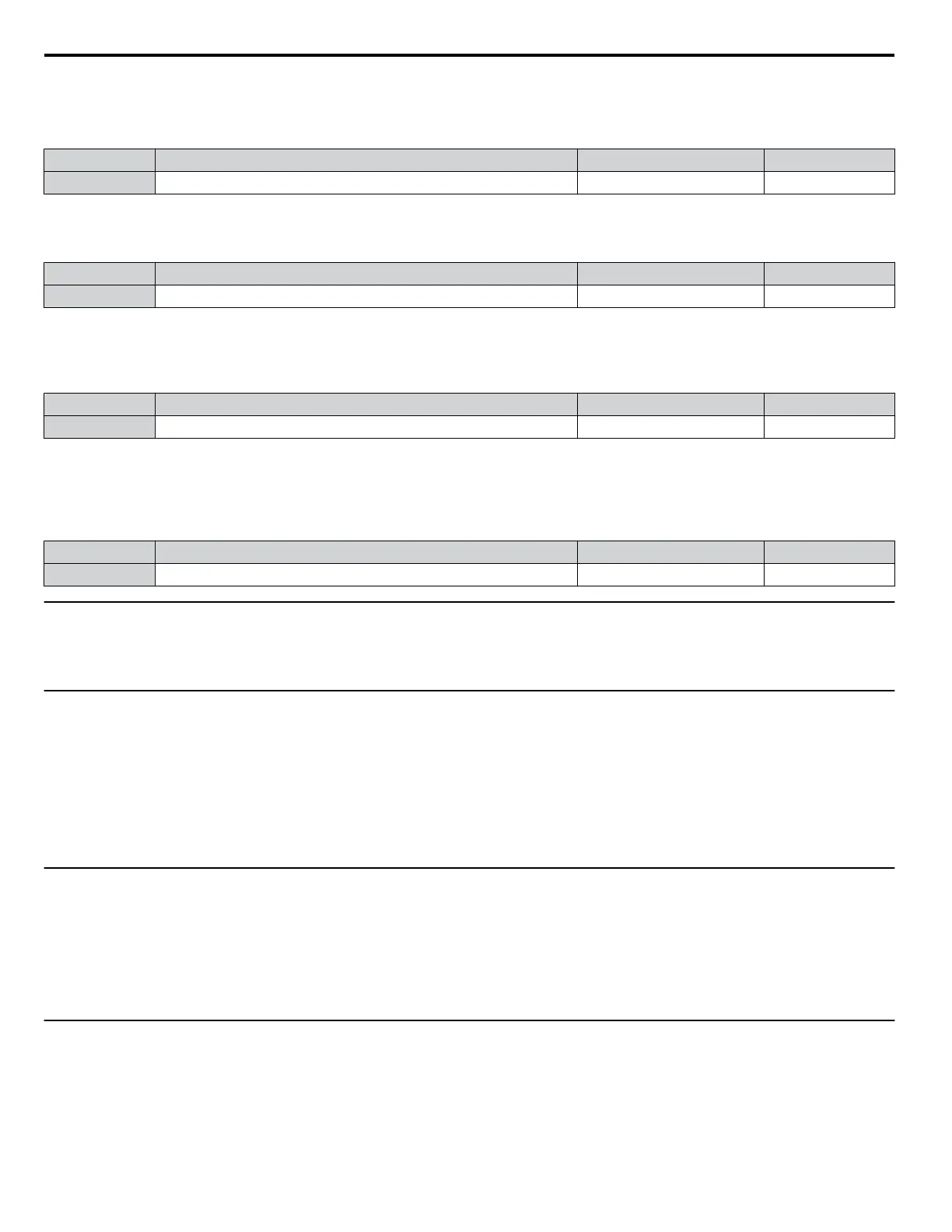
No. Name Setting Range Default
T1-05 Motor Base Frequency 0.0 to 240.0 Hz 60.0 Hz
n
T1-06: Number of Motor Poles
Sets the number of motor poles according to the motor nameplate value.
No. Name Setting Range Default
T1-06 Number of Motor Poles 2 to 48 4
n
T1-07: Motor Base Speed
Sets the motor rated speed according to the motor nameplate value. Enter the speed at base frequency when using a motor
with an extended speed range or if using the motor in the field weakening area.
No. Name Setting Range Default
T1-07 Motor Base Speed 0 to 14400 r/min 1750 r/min
n
T1-11: Motor Iron Loss
Provides iron loss information to determine the Energy Saving coefficient. T1-11 will first display the value for the motor iron
loss that the drive automatically calculated when the motor capacity was entered to T1-02. Enter the motor iron loss value
listed to T1-11 if the motor test report is available.
No. Name Setting Range Default
T1-11 Motor Iron Loss 0 to 65535 W 14 W
u
U1: Operation Status Monitors
Status monitors display drive status data such as output frequency and output current. Refer to U1: Operation Status
Monitors on page 332 for a complete list of U1-oo monitors and descriptions.
u
U2: Fault Trace
Use these monitor parameters to view the status of various drive aspects when a fault occurs.
This information is helpful for determining the cause of a fault. Refer to U2: Fault Trace on page 333 for a complete list of
U2-oo monitors and descriptions.
U2-oo monitors are not reset when the drive is initialized. Refer to o4-11: U2, U3 Initialization on page 192 for instructions
on how to reset these monitor values.
Note: Fault histories are not kept when CPF00, CPF01, CPF06, CPF24, oFA00, oFb00, oFC00, Uv1, Uv2, or Uv3 occur.
u
U3: Fault History
These parameters display faults that have occurred during operation as well as the drive operation time when those faults
occurred. Refer to U3: Fault History on page 334 for a complete list of U3-oo monitors and descriptions.
U3-oo monitors are not reset when the drive is initialized. Refer to o4-11: U2, U3 Initialization on page 192 for instructions
on how to reset these monitor values.
Note: Fault histories are not kept when CPF00, CPF01, CPF06, CPF24, oFA00, oFb00, oFC00, Uv1, Uv2, or Uv3 occur.
u
U4: Maintenance Monitors
Maintenance monitors show:
• Runtime data of the drive and cooling fans and number of Run commands issued
• Maintenance data and replacement information for various drive components
• kWh data
• Highest peak current that has occurred and output frequency at the time the peak current occurred
4.13 Advanced Drive Setup Adjustments
194
YASKAWA ELECTRIC TOEP C710616 45F YASKAWA AC Drive – Z1000 User Manual

 Loading...


