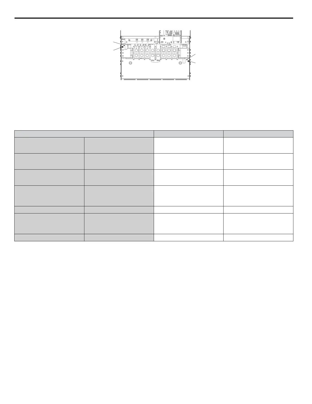
A – SW1 (ON)
B – Screw (OFF)
C – SW2 (ON)
Figure 3.37 EMC Filter Switch Location (4A0302)
If the SW1/SW2 screws are missing, install proper size screws with the proper tightening torque as shown in Table 3.6.
NOTICE: Do not use screws of different sizes in SW1 and SW2. Failure to comply may cause overheating.
Table 3.6 SW1/SW2 Screw Sizes and Tightening Torques
Drive Model SW1/SW2 Screw Size Tightening Torque
2A0011
2A0017
4A0005
4A0008
4A0011
M3 × 16
0.5 to 0.6 N•m
2A0024
2A0031
4A0014
4A0021
4A0027
M3 × 16
0.5 to 0.6 N•m
2A0046
2A0059
4A0034
4A0040
4A0052ooB
M3 × 16
0.5 to 0.6 N•m
2A0075
2A0088
2A0114
4A0052ooA
4A0065
4A0077
4A0096
M5 × 30
2 to 2.5 N•m
– 4A0124 M5 × 25
2 to 2.5 N•m
2A0143
2A0169
2A0211
2A0273
4A0156
4A0180
4A0240
M5 × 25
2 to 2.5 N•m
– 4A0302 M5 × 25
2 to 2.5 N•m
n
Wiring the Main Circuit Terminal
WARNING! Electrical Shock Hazard. Shut off the power supply to the drive before wiring the main circuit terminals. Failure to comply may
result in death or serious injury.
Wire the main circuit terminals after the terminal board has been properly grounded.
Models 2A0011 to 2A0273 and 4A0005 to 4A0302 have a cover placed over the 12/18 rectification terminals prior to shipment
to help prevent miswiring. Use wire cutters to cut away covers as needed for terminals.
Refer to Figure 3.4 on page 65 for details.
n
Main Circuit Connection Diagram
Refer to Main Circuit Connection Diagram on page 65 when wiring terminals on the main power circuit of the drive.
3.8 Main Circuit Wiring
90
YASKAWA ELECTRIC TOEP C710616 45F YASKAWA AC Drive – Z1000 User Manual

 Loading...


