n
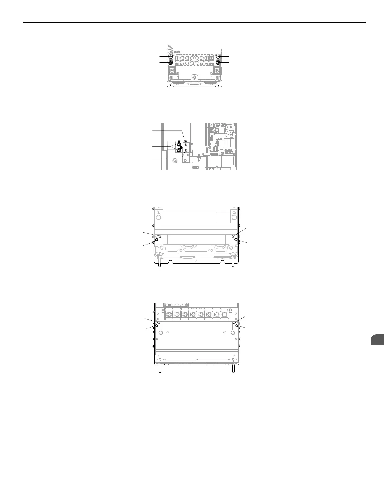
EMC Filter Switch Location
A – SW1 (ON)
B – Screw (OFF)
C – SW2 (ON)
Figure 3.33 EMC Filter Switch Location (2A0011 to 2A0059, 4A0005 to 4A0040, and 4A0052ooB)
A – SW1 (ON)
B – Screw (OFF)
C – SW2 (ON)
Figure 3.34 EMC Filter Switch Location (2A0075 to 2A0114, 4A0052ooA, and 4A0065 to 4A0096)
A – SW1 (ON)
B – Screw (OFF)
C – SW2 (ON)
Figure 3.35 EMC Filter Switch Location (4A0124)
A – SW1 (ON)
B – Screw (OFF)
C – SW2 (ON)
Figure 3.36 EMC Filter Switch Location (2A0143 to 2A0273 and 4A0156 to 4A0240)
3.8 Main Circuit Wiring
YASKAWA ELECTRIC TOEP C710616 45F YASKAWA AC Drive – Z1000 User Manual
89
3
Electrical Installation

 Loading...


