n
Output Terminals
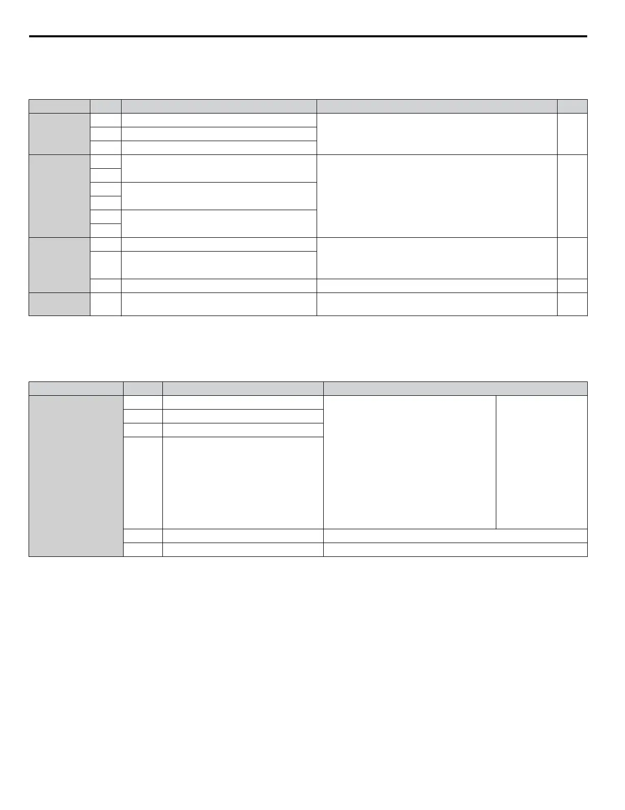
Table 3.8 lists the output terminals on the drive. Text in parenthesis indicates the default setting for each multi-function output.
Table 3.8 Control Circuit Output Terminals
Type No. Terminal Name (Function) Function (Signal Level) Default Setting Page
Fault Relay
Output
MA N.O.
30 Vdc, 10 mA to 2 A; 250 Vac, 10 mA to 2 A
Minimum load: 5 Vdc, 10 mA
–MB N.C. output
MC Fault output common
Multi-Function
Digital Output
<1>
M1
Multi-function digital output (During run)
30 Vdc, 10 mA to 2 A; 250 Vac, 10 mA to 2 A
Minimum load: 5 Vdc, 10 mA
–
M2
M3
Multi-function digital output (Zero speed)
M4
M5
Multi-function digital output (Speed Agree 1)
M6
Monitor
Output
FM Analog monitor output 1 (Output frequency) 0 to 10 V / 0 to 100%
4 to 20 mA / 0 to 100%
Voltage or current output must be selected by Jumper S5 and
H4-07 for FM and H4-08 for AM.
309
AM Analog monitor output 2 (Output current)
AC Monitor common 0 V –
External Power
Supply
+P External Power Supply 24 V (Max. 150 mA) –
<1> Refrain from assigning functions to digital relay outputs that involve frequent switching, as doing so may shorten relay performance life. Switching
life is estimated at 100,000 times (assumes 2 A, resistive load).
n
Serial Communication Terminals
Table 3.9 Control Circuit Terminals: Serial Communications
Type No. Signal Name Function (Signal Level)
Serial Communication
(APOGEE FLN,
BACnet, MEMOBUS/
Modbus, or Metasys
N2)
<1>
R+ Communications input (+)
APOGEE FLN, BACnet, MEMOBUS/
Modbus, or Metasys N2 communication: Use
an RS-422 or RS-485 cable to connect the
drive.
• APOGEE FLN
Comm. RS-422/
RS-485, 4.8 kbps
• BACnet Comm.
RS-485, max. 76.8
kbps
• MEMOBUS/
Modbus Comm.
RS-422/RS-485,
max. 115.2 kbps
• Metasys N2 Comm.
RS-422/RS-485, 9.6
kbps
R- Communications input (-)
S+ Communications output (+)
S- Communications output (-)
IG Communications ground 0 V
FE Option card ground –
<1> Enable the termination resistor in the last drive in an APOGEE FLN, BACnet, MEMOBUS/Modbus, or Metasys N2 network by setting DIP switch
S2 to the ON position. Refer to Control I/O Connections on page 100 for more information on the termination resistor.
3.9 Control Circuit Wiring
92
YASKAWA ELECTRIC TOEP C710616 45F YASKAWA AC Drive – Z1000 User Manual

 Loading...


