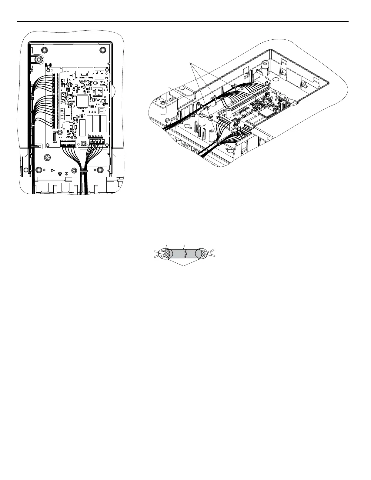
A – Cable tie hole B – Cable hook
Figure 3.45 Control Terminal Wiring (2A0143 to 2A0396 and 4A0156 to 4A0590)
When setting the frequency by analog reference from an external potentiometer, use shielded twisted-pair wires (preparing
wire ends as shown in Figure 3.46) and connect the shield to the ground terminal of the drive.
A – Drive side
B – Insulation
C – Control device side
D – Shield sheath (insulate with tape)
E – Shield
Figure 3.46 Preparing the Ends of Shielded Cables
NOTICE: The analog signal wiring between the drive and the operator station or peripheral equipment should not exceed 50 meters when
using an analog signal from a remote source to supply the frequency reference. Failure to comply could result in poor system performance.
3.9 Control Circuit Wiring
98
YASKAWA ELECTRIC TOEP C710616 45F YASKAWA AC Drive – Z1000 User Manual

 Loading...


