If a lower reference than this value is entered, the drive will run at the limit set to d2-02. If the drive is started with a lower
reference than d2-02, it will accelerate up to d2-02.
No. Parameter Name Setting Range Default
d2-02 Frequency Reference Lower Limit 0.0 to 110.0% 0.0%
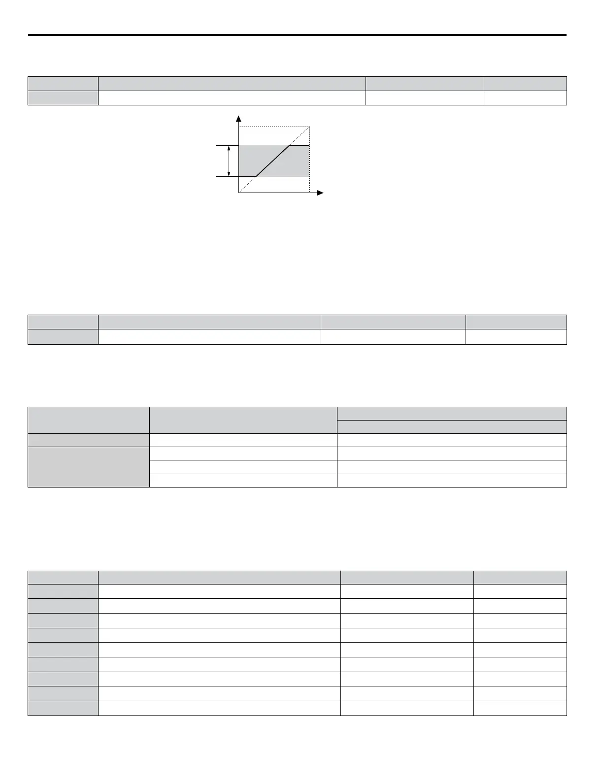
Internal frequency
reference
d2-01
Operating
range
Frequency Reference Upper Limit
Set frequency reference
Frequency Reference Lower Limit
d2-02
Figure 4.20 Frequency Reference: Upper and Lower Limits
n
E1-01: Input Voltage Setting
Adjusts the levels of some protective features of the drive (overvoltage, Stall Prevention, etc.). Set this parameter to the nominal
voltage of the AC power supply.
NOTICE: Set parameter E1-01 to match the input voltage of the drive. Drive input voltage (not motor voltage) must be set in E1-01 for the
protective features to function properly. Failure to set the correct drive input voltage will result in improper drive operation.
No. Parameter Name Setting Range Default
E1-01 Input Voltage Setting
190 to 240 V
<1>
230 V
<1>
<1> Values shown are specific to 200 V class drives. Double the value for 400 V class drives.
E1-01 Related Values
The input voltage setting determines the overvoltage and undervoltage detection levels, the KEB function, and the overvoltage
suppression function.
Voltage Setting Value of E1-01
(Approximate Values)
Uv Detection Level (L2-05)
200 V Class All settings 190 V
400 V Class
Setting > 460 V 440 V
Setting ≥ 400 V
380 V
Setting < 400 V 350 V
n
V/f Pattern Settings E1-04 to E1-13
If E1-03 is set to a preset V/f pattern (i.e., a value other than F), the user can monitor the V/f pattern in parameters E1-04
through E1-13. To create a new V/f pattern, set E1-03 to F. Refer to V/f Pattern on page 135 for an example custom V/f
pattern.
Note:
Certain E1-oo parameters might not be visible depending on the control mode. Refer to Parameter List on page 281 for details.
No. Parameter Name Setting Range Default
E1-04 Maximum Output Frequency 40.0 to 240.0 Hz
<1>
E1-05 Maximum Voltage
0.0 to 255.0 V
<2> <1>
E1-06 Base Frequency 0.0 to 240.0 Hz
<1>
E1-07 Middle Output Frequency 0.0 to 240.0 Hz
<1>
E1-08 Middle Output Frequency Voltage
0.0 to 255.0 V
<2> <1>
E1-09 Minimum Output Frequency 0.0 to 240.0 kHz
<1>
E1-10 Minimum Output Frequency Voltage
0.0 to 255.0 V
<2> <1>
E1-11 Middle Output Frequency 2 0.0 to 240.0 Hz
0.0 Hz
<3>
E1-12 Middle Output Frequency Voltage 2
0.0 to 255.0 V
<2>
0.0 V
<3>
4.7 Basic Drive Setup Adjustments
134
YASKAWA ELECTRIC TOEP C710616 45F YASKAWA AC Drive – Z1000 User Manual

 Loading...


