Output Frequency
C1-11
Accel/Decel Time
Switch Frequency
C1-03
setting
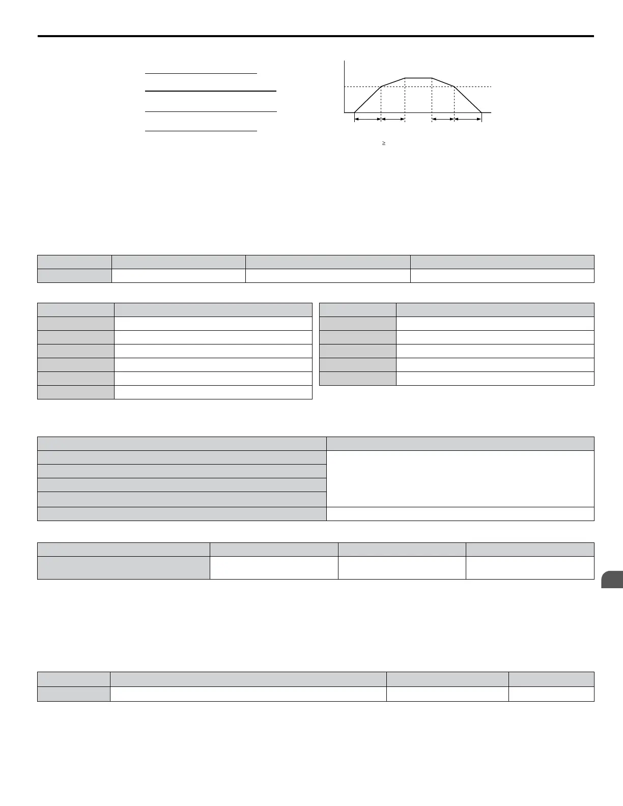
When the output frequency C1-11, drive uses Accel/Decel Time 1 (C1-01, -02)
When the output frequency < C1-11, drive uses Accel/Decel Time 2 (C1-03, -04)
C1-01
setting
C1-02
setting
C1-04
setting
C1-03 =
(accel time from 0 Hz to C1-11) × (E1-04)
C1-11
C1-01 =
(accel time between C1-11 and E1-04) × (E1-04)
(E1-04 - C1-11)
C1-02 =
(decel time between E1-04 and C1-11) × (E1-04)
(E1-04 - C1-11)
C1-04 =
(decel time from C1-11 to 0 Hz) × (E1-04)
C1-11
Figure 4.19 Accel/Decel Time Switching Frequency
n
C6-02: Carrier Frequency Selection
Sets the switching frequency of the drive output transistors. Changes to the switching frequency lower audible noise and reduce
leakage current.
Note: Increasing the carrier frequency above the default value automatically lowers the drive current rating.
No. Parameter Name Setting Range Default
C6-02 Carrier Frequency Selection 1 to 5; 7 to 9; A to F Determined by A1-02 and o2-04
Settings:
C6-02 Carrier Frequency
1 2.0 kHz
2 5.0 kHz
3 8.0 kHz
4 10.0 kHz
5 12.5 kHz
7 Swing PWM 1
C6-02 Carrier Frequency
8 Swing PWM 2
9 Swing PWM 3
A Swing PWM 4
B to E No setting possible
F User defined
Note: Swing PWM uses a carrier frequency of 2.0 kHz as a base, then applies a special PWM pattern to reduce the audible noise.
Guidelines for Carrier Frequency Parameter Setup
Symptom Remedy
Speed and torque are unstable at low speeds
Lower the carrier frequency.
Noise from the drive affects peripheral devices
Excessive leakage current from the drive
Wiring between the drive and motor is too long
<1>
Audible motor noise is too loud Increase the carrier frequency or use Swing PWM.
<1> The carrier frequency may need to be lowered if the motor cable is too long. Refer to the following table.
Wiring Distance Up to 50 m Up to 100 m Greater than 100 m
Recommended setting value for C6-02 1 to F (up to 12.5 kHz)
1 to 2 (up to 5 kHz),
7 (Swing PWM)
1 (up to 2 kHz), 7 (Swing PWM)
Note: The maximum cable length is 100 m when using OLV/PM (A1-02 = 5).
n
d2-01: Frequency Reference Upper Limit
Sets the maximum frequency reference as a percentage of the maximum output frequency. This limit applies to all frequency
references.
Even if the frequency reference is set to a higher value, the drive internal frequency reference will not exceed this value.
No. Parameter Name Setting Range Default
d2-01 Frequency Reference Upper Limit 0.0 to 110.0% 100.0%
n
d2-02: Frequency Reference Lower Limit
Sets the minimum frequency reference as a percentage of the maximum output frequency. This limit applies to all frequency
references.
4.7 Basic Drive Setup Adjustments
YASKAWA ELECTRIC TOEP C710616 45F YASKAWA AC Drive – Z1000 User Manual
133
4
Start-Up Programming
& Operation

 Loading...


