Target setpoints 1 to 8
Output limiter
Manual operation
Manual preset output
Input error preset output
Preset output
(ON in AUT, MAN, and STOP)
AUTO, MANCAS
AUTO
When sensor
burnout occurs
Normal
MAN
RUNSTOP
SP ramp rate
SP limiter
DI16PV RSP
Input type
Input unit
Input range/scale
Analog input bias
Square root extraction
Analog input filter
Input type
Input unit
Input range/scale
Analog input bias
Square root extraction
Analog input filter
10-seg. linearizer approx./bias
PV input bias
PV input filter
Output limiter
A.BS
A.FL
BS
FL
PMD An, Bn
10-seg. linearizer approx./bias
PMD An, Bn
10-seg. linearizer approx./bias
PMD An, Bn
CNT ALG
UPR, DNR TMU
SPNO SP
SPH, SPL
A.SR A.LC
UNIT
IN
RH, RL SDP SH, SL
A.BS
A.FL
A.SR A.LC
UNIT
IN
RH, RL SDP SH, SL
EPO
OH, OL
OH, OL OLMT
PO
S/R
MPON
OT
Equipped as standard
Equipped as standard Equipped as standard
Heater break alarm
HAL2HAL1
Heater break
alarm 1
Heater break
alarm 2
Current or
voltage pulse
Relay
LPS
24 V loop
power supply
Current
OUTOUT RET AL3AL2AL1
Tracking
switch
PMD
OU.H OU.L
An, Bn
Split computation
10-seg. linearizer approx./bias
RET.H RET.L
PMD An, Bn
Split computation
10-seg. linearizer approx./bias
OUT retransmission output
O1RS
Target setpoint output
RTS
Alarm Tracking switch
Output terminal assignment
DI3DI2DI1
A/M
Control computation
(to Loop-1 controller)
(Current when retransmission output)
Ratio bias computation
RT RBS
Remote input filter
RFL
PV input
Equipped as standard
Cascade input
(from Loop-1 controller)
Contact inputs
(from Loop-1 controller)
Cascade (OFF→ON)
Automatic (OFF→ON)
Manual (OFF→ON)
(to Loop-1 controller)
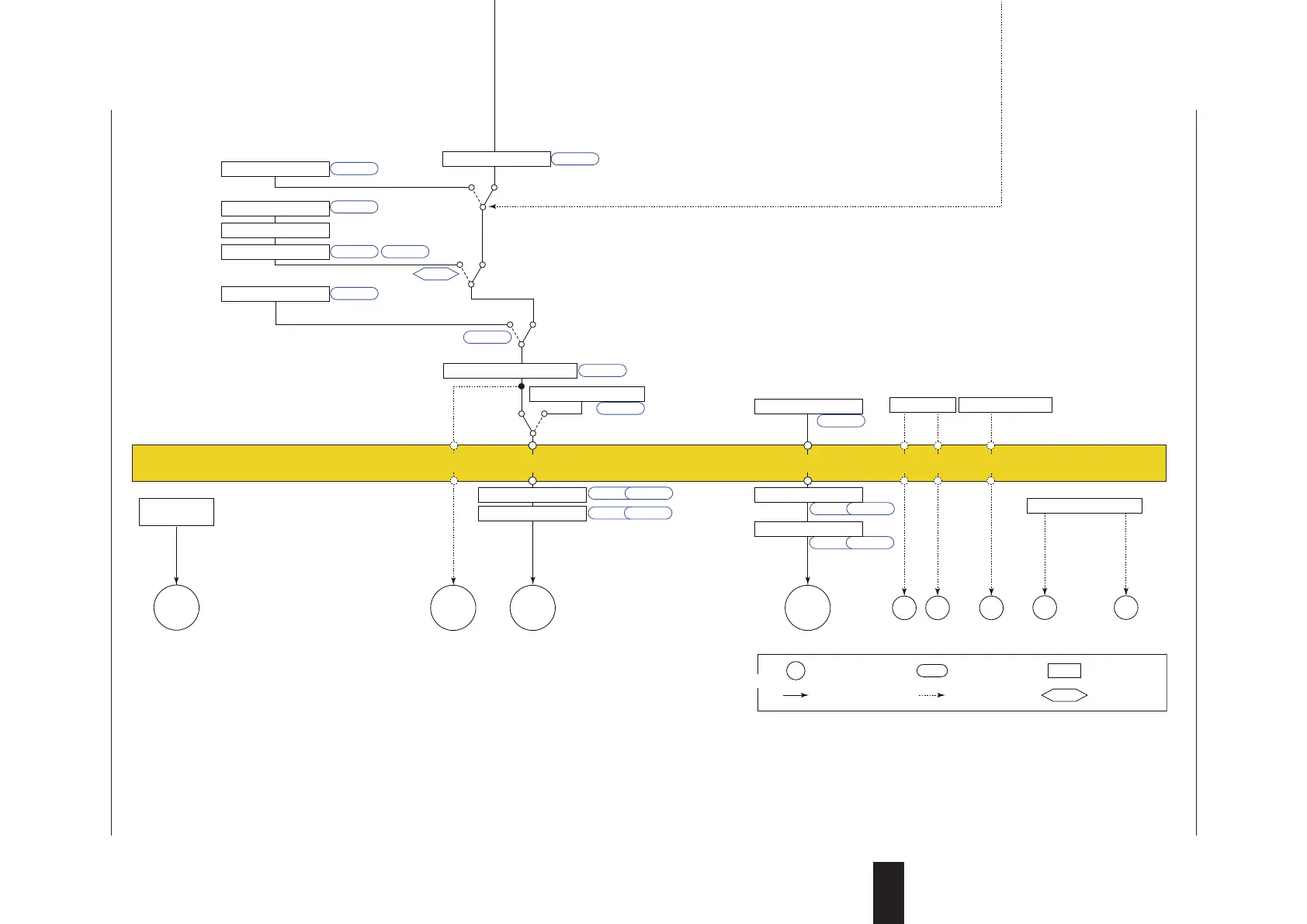
Terminal Parameter Function
Analog signal Contact signal Front panel key
Legend
Alarm 1
(PV high limit)
Alarm 2
(PV low limit)
* After the control output terminal is specified by the parameter OT,
other current output terminals can be used as retransmission output.
PV display SP display
Input ladder calculation program (signal goes to the control computation as is when without ladder program). For ladder program, see the LL50A Parameter Setting Software User’s Manual.
Output ladder calculation program (signal goes to the output as is when without ladder program). For ladder program, see the LL50A Parameter Setting Software User’s Manual.
Switch from CAS (contact ON) to AUTO (contact
OFF) at FAIL of Loop-1 controller
(For Detailed model)
Cascade input can be used when UT55A/UT52A optional
suffix code /R1 or /RCH1.
(For Standard model)
Cascade input can be used when UT55A suffix code: Type 2
= 1, 2, 4, 5, or 7; UT52A suffix code: Type 2 = 1 or 2.
(For Detailed model)
DI16 is equipped when UT55A/UT52A optional suffix code
/R1 or /RCH1.
(For Standard model)
DI16 is equipped when UT55A suffix code: Type 2 = 1, 2, 4,
5, or 7; UT52A suffix code: Type 2 = 1 or 2.
Universal input (E1-terminal area) can be used
when UT55A/UT52A optional suffix code /U1.
However, DI16 does not exist.

 Loading...
