10-4
IM 05P01C31-01EN
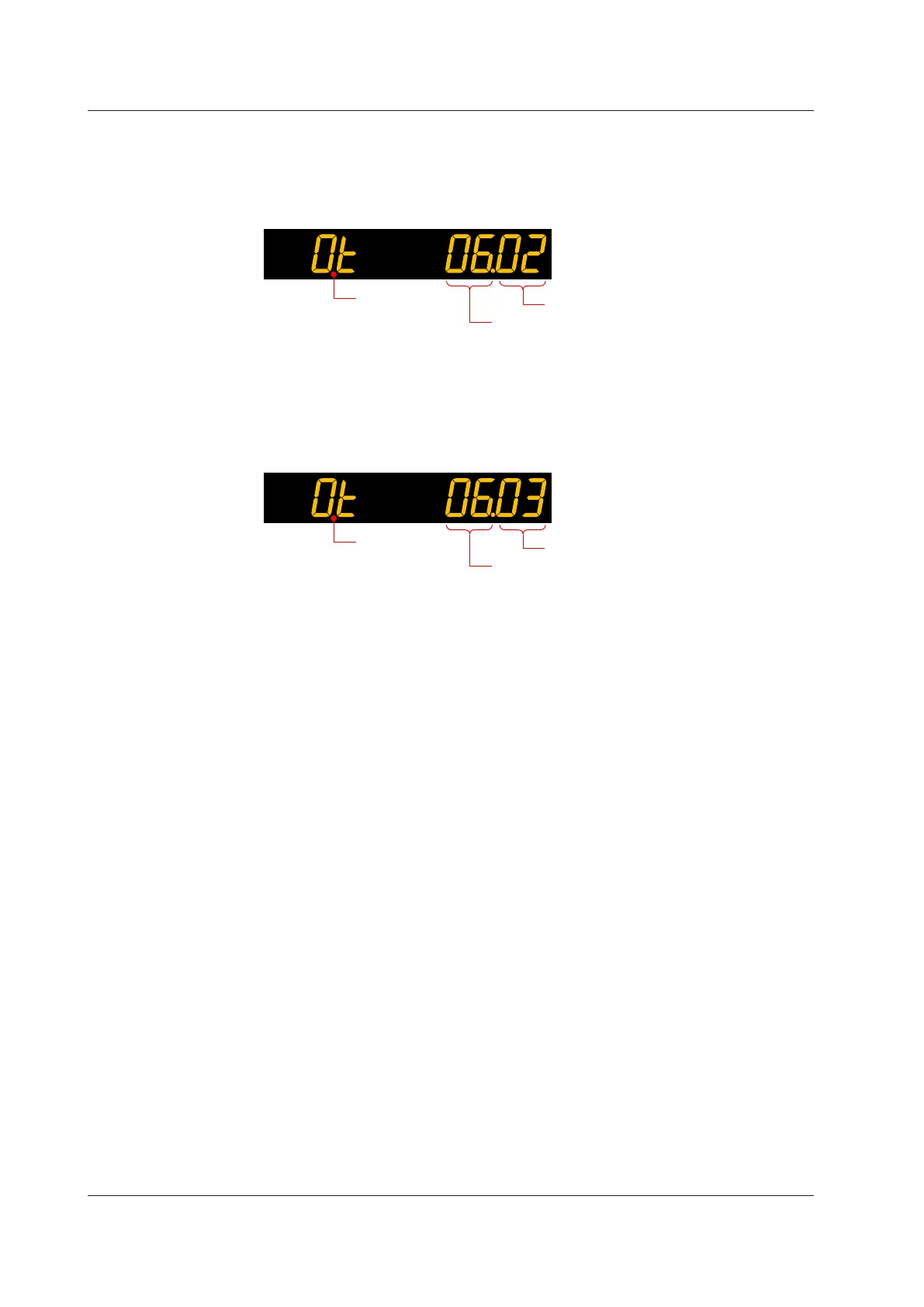
Heating/coolingControlOutputofHeating/coolingType
The figure below shows an example of setting the current output of the OUT terminal
to the heating-side control output terminal and type, and setting the relay output of the
OUT2 terminal to the cooling-side control output terminal and type.
Heating side: Set “02” to lower two digits. Cooling side: Set “06” to upper two digits.
Heating-side control output terminal and type
Cooling-side control output terminal and type
Symbol
Two-positionTwo-levelControlOutput(forHeating/coolingTypeOnly)
The figure below shows an example of setting the relay output of the OUT terminal to the
control output terminal and type of main setting, and setting the relay output of the OUT2
terminal to the control output terminal and type of sub-setting.
Main setting side: Set “03” to lower two digits. Sub-setting side: Set “06” to upper two
digits.
Main setting side control output terminal and type
Sub-setting side control output terminal and type
Symbol
PositionProportionalOutput(forPositionProportionalTypeOnly)
When Position proportional type is specified, the output form is fixed to the position
proportionaloutputand
settingisnotnecessary.Adjustmentofthevalvepositionis
necessary.
► Valvepositionadjustment:10.16AdjustingMotor-operatedValvePosition(PositionProportional
Output)
10.1SettingControlOutputType

 Loading...
