18-2
IM 05P01C31-01EN
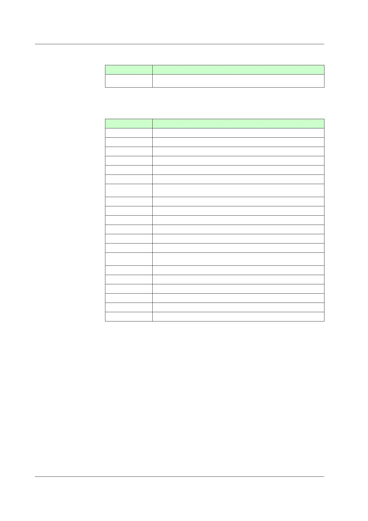
FunctionofEachMenu
Menusymbol Function
MODE
Operation mode (STOP/RUN switch, REMOTE/LOCAL switch, Auto-tuning
switch, SP number selection, etc.)
The parameters in the menu of the following table indicate the parameters to set the
functions necessary for operation. The symbol in parentheses are shown on Group
display.
Menusymbol Function
CS SELECT parameter
SP SP and alarm setpoint
SPS SP-related function
ALRM Alarm function
PVS PV-relatedfunction
PID PID setting
TUNE
Super, Super 2, Sample PI control, non-linear PID control, Feedforward
control, anti-reset windup, output velocity limiter, and manual preset output
ZONE Zone
control
SP(LP2) SP and alarm setpoint (Loop 2)
SPS
(LP2) SP-related function (Loop 2)
ALRM(LP2) Alarm function (Loop 2)
PVS(LP2) PV-relatedfunction(Loop2)
PID(LP2) PID setting (Loop 2)
TUNE(LP2)
Super, Super 2, non-linear PID control, anti-reset windup, output velocity
limiter, manual preset output (Loop 2)
ZONE(LP2) Zonecontrol
(Loop2)
PPAR P parameter (for ladder program)
PYS1(1) 10-segmentlinearizer
1
PYS2(2) 10-segmentlinearizer2
PYS3(3) 10-segmentlinearizer3
PYS4(4) 10-segmentlinearizer4
18.1ParameterMap

 Loading...
