3-3
IM 05P01C31-01EN
PartNames
3
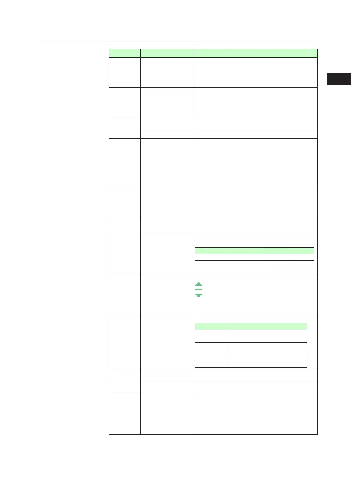
No.ingure Name Description
(1)
PVdisplay
(white
orred)
DisplaysPV.
Displays an error code if an error occurs.
Displays the scrolling guide in the Menu Display and
Parameter Setting Display when the guide display ON/
OFF is set to ON.
(2)
Group display
(green)
Displays a group number (1 to 8, or R) and terminal area
(E1 to E4).
1 to 8 represent SP numbers in the Operation Display.
R and E1 to E4 are displayed in the Parameter Setting
Display.
(3)
Symbol
display
(orange)
Displays a parameter symbol.
(4) Data
display(orange) Displays a parameter setpoint and menu symbol.
(5)
Bar-graph
display
(orange
andwhite)
Displays control output value (OUT) and measured input
value(PV).
The data to be displayed can be set by the parameter.
Initial value: upper bar (deviation), lower bar (control
output, internal computed value in Position proportional
control);
in Heating/cooling control, upper bar (heating-side control
output), lower bar (cooling-side control output)
(6)
Eventindicator
(orange)
UT55
A: Lit when the alarms 1 to 8 occur. (Initial value: 1 to
4)
UT52A: Lit when the alarms 1 to 4 occur.
Event displays other than alarms can be set by the
parameter.
(7)
Keynavigation
indicator
(green)
Lit or blinks when the Up/Down or Left/Right arrow key
operation is possible.
(8)
Parameter
display
level
indicator
(green)
Displays the setting conditions of the parameter display
level function.
Parameterdisplaylevel EASY PRO
Easy setting mode Lit Unlit
Standard setting mode Unlit Unlit
Professional setting mode Unlit Lit
(9)
Deviation
indicator
(for
UT55Aonly)
(green)
Displaysthestatusofadeviation(PV-SP).
: Lit if a deviation exceeds the deviation display band.
:
Lit when a deviation is within the deviation display band.
:
Lit if a deviation falls below the deviation display band.
The deviation indicator is unlit if the Displays other than
the Operation Display or SELECT Display are shown.
Deviation display band can be set by the parameter.
(10)
Status indicator
(greenandred)
Displays the operating conditions and control status.
Display Description
REM Lit when in remote mode (REM).
CAS Lit when in cascade mode (CAS).
PRG Unused
STOP Lit when in stop mode (STOP).
MAN
Lit when in manual mode (MAN).
Blinks during auto-tuning.
(11) Security
indicator(red)
Lit if a password is set.
The setup parameter settings are
locked.
(12)
Ladder operation
indicator(green)
Lit while the ladder program operation is executed.
(13
Loop 2 indicator
(LP2lamp)
(green)
Lit when the control mode is Cascade control.
In the Operation Display
, the LP2 lamp is lit while the
Loop-2 data is displayed on Setpoint display.
In the Parameter Setting Display
, the LP2 lamp indicates
the loop of displayed menu symbol or parameter symbol.
The LP2 lamp is lit while the Loop-2 menu symbol or
parameter symbol is displayed.
3.1NamesandFunctionsofDisplayParts

 Loading...
