892 J006 MNAH | PGC5000 G EN 2 | 105
When the button for a specific output module is selected from the Function Select list, the appropriate
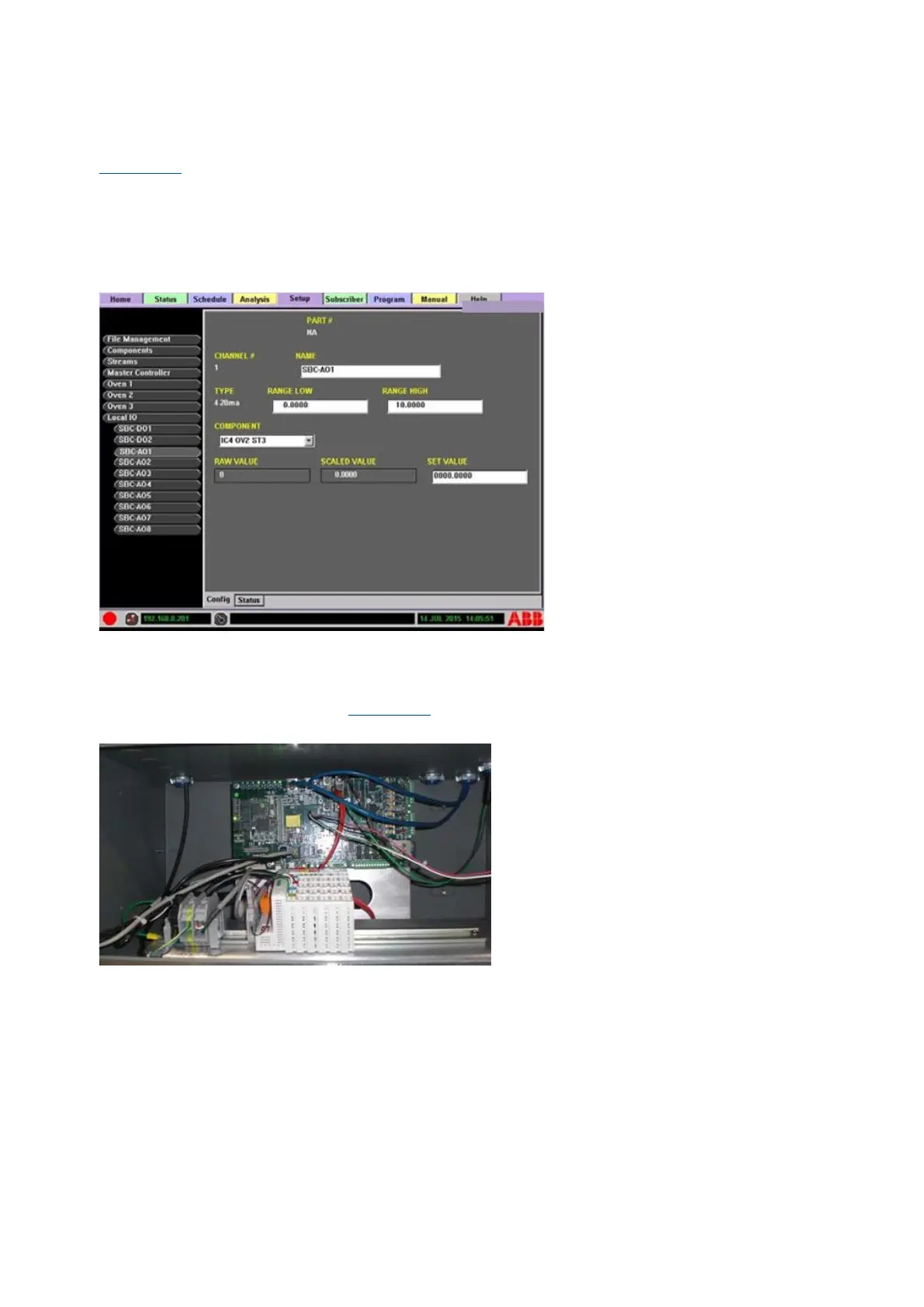
Module Configuration display appears. Individual channels are listed on the buttons below the output
module name. The button names can be edited for reference.
Figure 5-18 illustrates the local output display. The editable areas are:
⎯ NAME: reference name, used for the button name
⎯ RANGE LOW: analog output low limit
⎯ RANGE HIGH: analog output high limit
⎯ COMPONENT: configured component drop-down list
⎯ SET VALUE: user-set value, used to test the module
Figure 5-18: Local Output Display
5.9.3 Internal input/output option
The Master Controller allows the placement of optional Wago input/output modules internally, in front
of the Single Board Computer (see Figure 5-19) and accessed through the front door.
Figure 5-19: Internal Input/Output Module Locations
The internal I/O option connects to the SBC CAN Interface Card via an electrical cable. Configuration
of the option is completed and tested at the factory prior to shipment. The I/O option contains one
Control Module, one End Module, and up to 18 input/output modules. The input/output modules are
referred to in the manual and analyzer as Wago modules. The following input/output modules are
available (color code at the top of each module indicates the type of module):
⎯ 2 channel analog output, 4 to 20 mA (blue)
⎯ 4 channel analog output, 4 to 20 mA (blue)
⎯ 4 channel analog output, ±10 V, 0 to 10 V (blue)
⎯ 2 channel analog input, AC/DC 0 to 10 (green)
⎯ 2 channel analog input, 4 to 20 mA (green)
⎯ 4 channel digital output, 24 V, with low-side switching (red)
⎯ 4 channel digital output, 24 V, with high-side switching (red)