28 | PGC5000 GEN 2 | 892 J006 MNAH
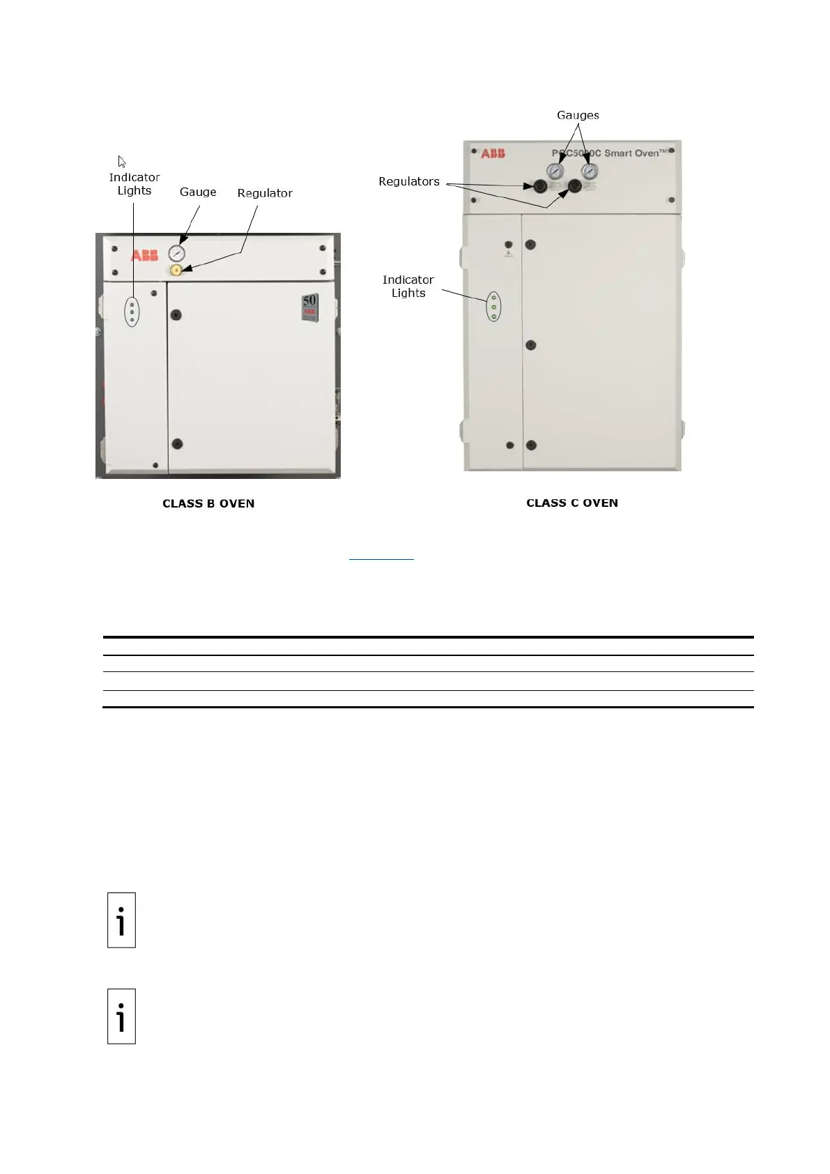
Figure 3-6: Typical ovens
3.3.1 Oven LED indicators
Each oven has three LED indicators (see Figure 3-6) which show the current status of the oven.
⎯ If the LEDs are not lit, check power to the unit.
⎯ If the top LED is green and flashing, the system is initializing.
⎯ For all other situations use the following table.
Table 3-3: LED indicators
Low Oven Air and/or Carrier Gas Alarm
3.3.2 Oven regulators and gauges
If there is one pair of regulators and gauges, they control both oven and heater air.
If there are two pairs of regulators and gauges, one pair controls oven and heater air and the other
pair controls purge and valve air.
3.4 Start the analyzer
1. Visually inspect the analyzer for inoperative or damaged gauges, loose or damaged
connections, and overall condition.
2. Turn on the instrument air at its source.
IMPORTANT NOTE: Refer to the Data Package to ensure that air supply at the specified pressure
is provided to the INSTRUMENT AIR inlet. The purge air and heater air pressures should be as
specified on the label below the corresponding regulator.
3. Turn on carrier gas at its source.
IMPORTANT NOTE: Refer to the Data Package to ensure that the specified carrier gas is provided
at the specified pressure to each CARRIER inlet.
If the analyzer is equipped with enclosure purge, refer to the sales order tag for specified flow rate
and purge time before applying electrical power