84 | PGC5000 GEN 2 | 892 J006 MNAH
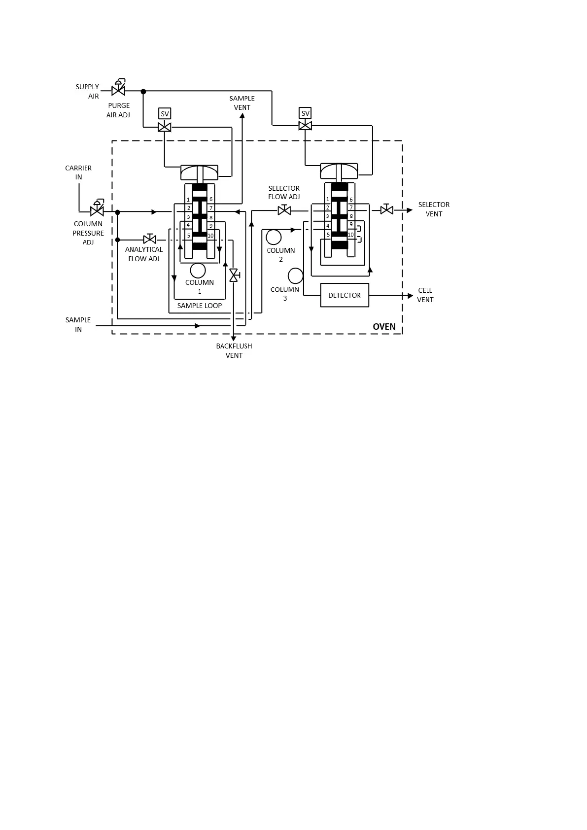
Figure 5-1: Typical analytical flow system diagram
The volume of sample is determined by the sample loop. When the valve switches, the sample passes
into Column 1, to Column 2 and into the detector cell, where it is converted to an electrical signal.
Column 1 performs preliminary separation to remove the heavier non-measured components, which
are then backflushed to vent. Column 2 separates the components to be measured, which elute
sequentially to the selector valve. The selector valve determines which components will be measured.
The sample output from Column 2 goes through Column 3 to the detector for measurement. When the
valve switches, the sample not being measured is flushed through the Selector to Vent.
The carrier gas has three purposes: to purge the columns and cell prior to introducing a sample, to
sweep the sample into the detector cell, and to backflush the backflush column.
The sample system, together with the PGC, controls the calibration sample input. The sample system
flow and pressure control depend on the sample system configuration.
5.2 Detectors
Standard detectors are the Flame Ionization Detector (FID), Thermal Conductivity Detector (TCD),
and Flame Photometric Detector (FPD). These detectors may be used separately, in combination, or as
dual detectors. An optional Dielectric Barrier Discharge Ionization Detector (DBDID) is also available.
5.2.1 Flame ionization detector (FID)
The FID cell reduces the physical sample to an electrical signal. The cell consists of a polarized jet, a
collector, and a chamber in which hydrogen fuel and sample are burned in air. A current, whose
magnitude is proportional to the concentration of the sample, flows between the jet and the collector.
This current goes to the FID Amplifier Assembly.
The FID Amplifier Assembly provides ignition control for the FID cell and amplification of the detector
cell output signal prior to routing the signal to the control section for signal processing. It consists of a
power supply, igniter assembly, electrometer amplifier, and associated circuitry. The power supply
provides the necessary dc voltages for the FID Amplifier Assembly and FID.
The igniter assembly provides control for the igniter in the detector cell. In the event of a flame-out,
the thermocouple senses the flame-out, illuminates the flame-out LED, and sends a message to the
igniter assembly, which re-ignites the flame. The electrometer amplifier takes the FID cell’s output,
amplifies it, and sends it to the control section for signal processing.