74 | PGC5000 GEN 2 | 892 J006 MNAH
⎯ LOW LIMIT: Minimum Alarm Level
⎯ HIGH LIMIT: Maximum Alarm Limit
⎯ ZONE TYPE: Isobaric, Programmable (set at the factory)
The Status subtab displays the state and date and time of all active indicators in the EPC group of
indicators. Diagnostic information is also displayed.
4.6.11 Detector amplifier
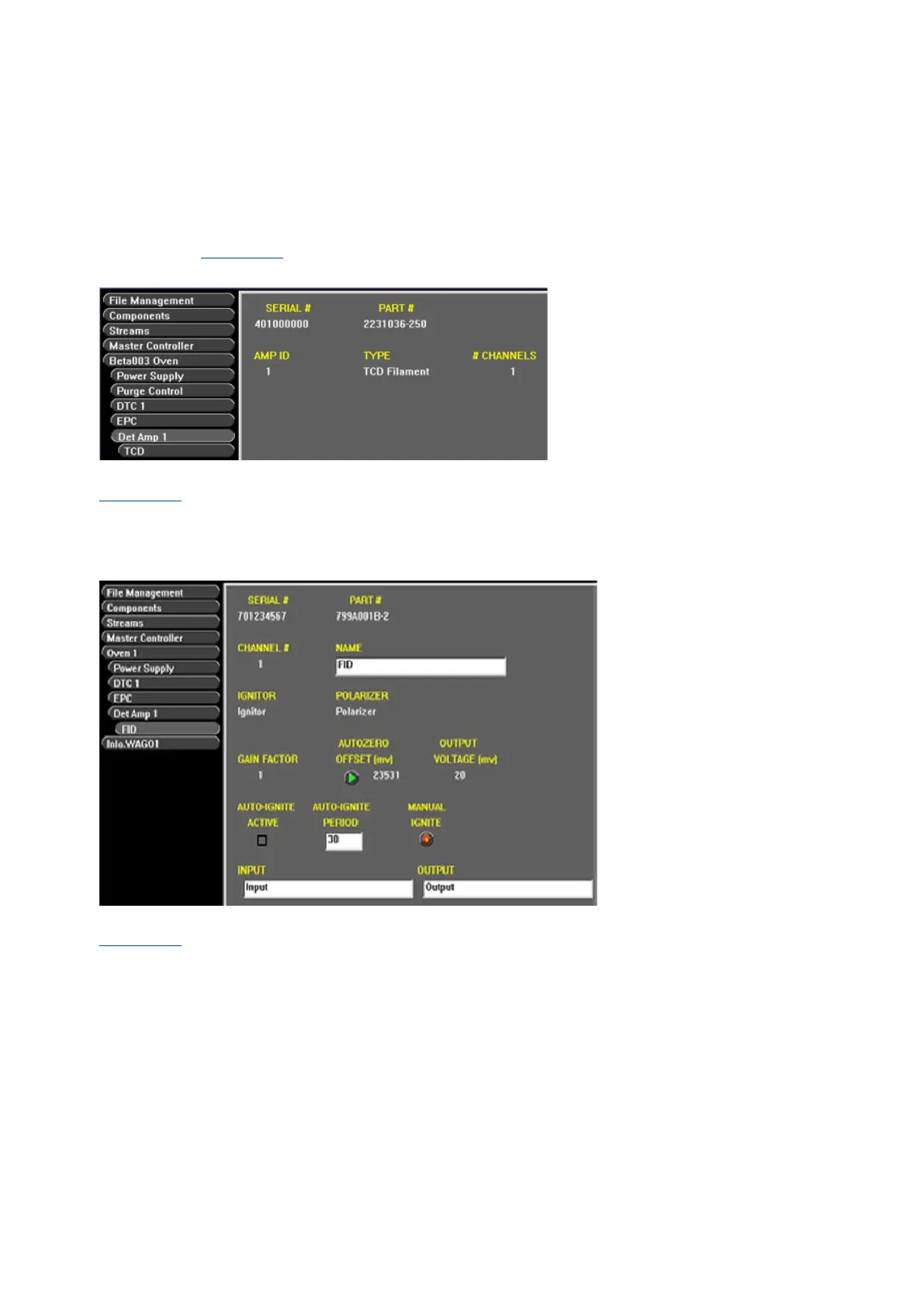
The Oven>DetAmp subtab displays Serial Number, Part Number, amplifier ID, type and number of
channels (see Figure 4-43).
Figure 4-43: Detector amplifier configuration
The Oven>DetAmp>FID Configuration subtab displays the Serial, Part, and Channel number (see
Figure 4-44). It also displays the Igniter, Polarizer, Gain factor and Output Voltage. A manual
AUTOZERO button is provided. Set the AUTO-IGNITE ACTIVE option and adjust the AUTO-IGNITE
PERIOD (seconds) or select MANUAL IGNITE to ignite the detector manually from this screen. The
AUTO-IGNITE PERIOD is the time in seconds before you try to re-ignite the burner if the flame is out.
Figure 4-44: FID configuration
The Oven>DetAmp>FPD Configuration subtab displays the Serial, Part, and Channel number (see
Figure 4-45). It also displays the Igniter, Polarizer, Gain factor and Output Voltage. A manual
AUTOZERO button is provided. Set the AUTO-IGNITE ACTIVE option or select MANUAL IGNITE to
ignite the detector manually from this screen.