24 | PGC5000 GEN 2 | 892 J006 MNAH
Figure 3-1: Master Controller
3.2.1 Touchscreen layout
Figure 3-2 illustrates the basic Master Controller display layout and functionality. Use the touchscreen
to navigate.
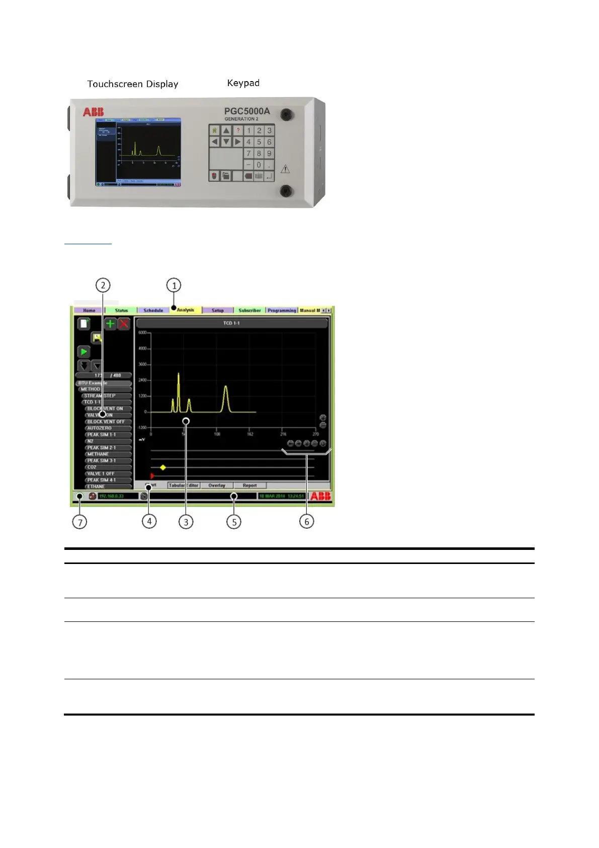
Figure 3-2: Basic Analyzer Screen Layout
Legend: Basic Analyzer Screen Layout
Tabs – Select a tab using the cursor to
navigate between system operation and
configuration displays.
System Information Bar – Displays current
analyzer information.
Function Selectors – Displays buttons and
action icons for the selected tab.
Zoom Control – Increases or decreases the scale
of the display.
Subtab Display Area – Provides specific
information relating to the tab and/or
subtab selected.
System Condition Status Indicator:
⎯ Green = Normal
⎯ Yellow = Warning
⎯ Red = Alarm
⎯ Blue = Information Only
Subtabs – Each subtab displays additional
information applicable for the main tab
selected.