106 | PGC5000 GEN 2 | 892 J006 MNAH
⎯ 2 channel relay output, AC 230 V, DC 30 V (red)
⎯ 4 channel digital input, DC 5 V, with high-side switching (yellow)
⎯ 4 channel digital input, 24 V (yellow)
The Control Module (grey) is at the left end of the string of Wago modules and the End Module (grey)
is at the right end. When the button for a specific I/O module is selected from the Function Select list,
the appropriate Module Configuration display appears (Figure 5-20 shows the Digital I/O). Individual
I/O channels are listed on the button below the I/O module name. The button names can be edited for
reference.
Figure 5-20: Internal onboard I/O Display
Input/output modules are shown in the following paragraphs, with the editable areas noted.
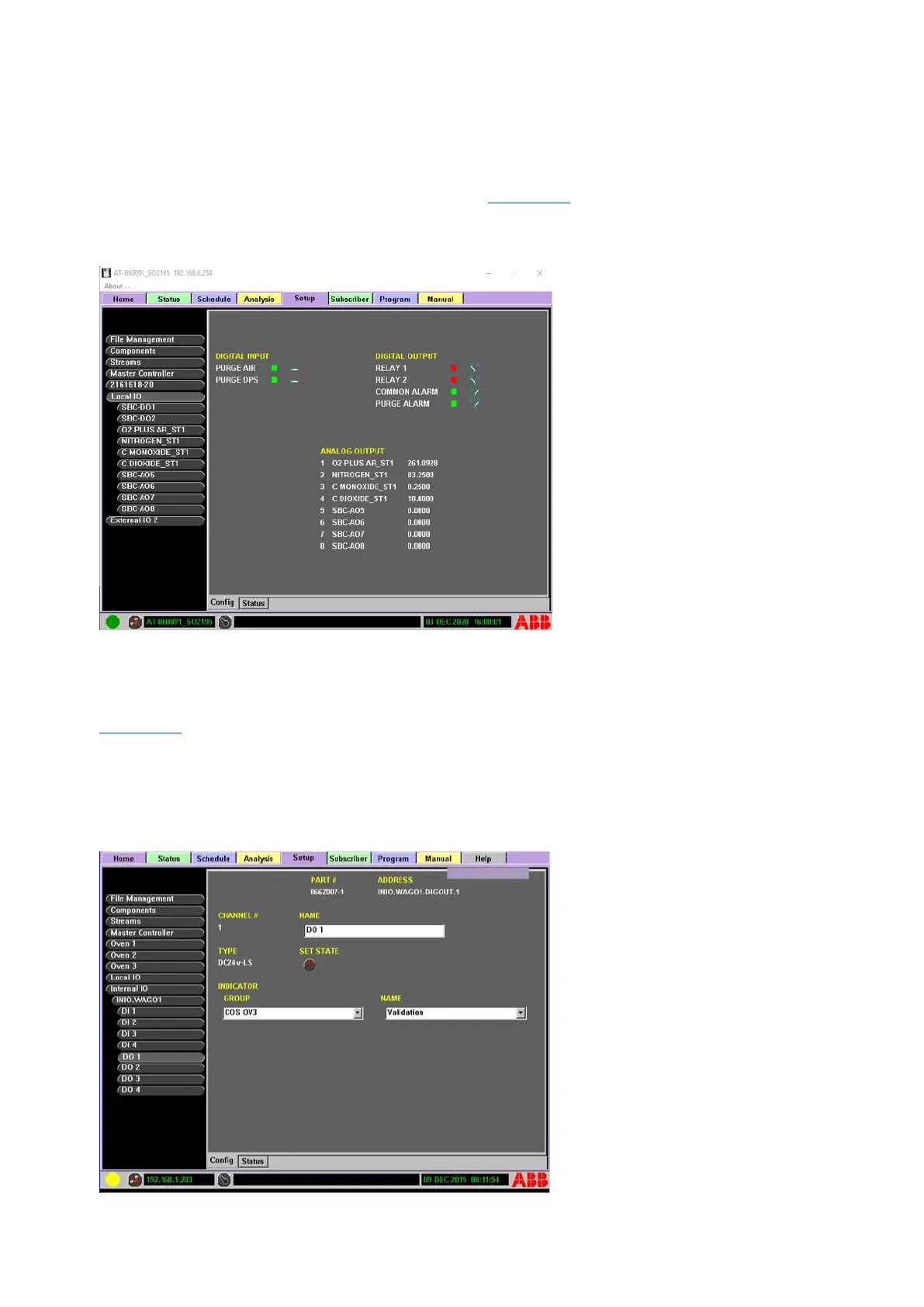
5.9.4 Digital output
Figure 5-21 illustrates the digital I/O display, with a digital output channel selected. The editable areas
are:
⎯ NAME: reference name used for the button name
⎯ SET STATE: toggle switch used to set input On or Off
⎯ GROUP: indicator group assignment
⎯ NAME: assigned indicator name with the group
Figure 5-21: Internal Digital Output Display