892 J006 MNAH | PGC5000 G EN 2 | 69
To display information about the oven’s ancillary equipment, select the associated button.
4.6.8 Oven buttons
As with the Master Controller button, the Oven buttons display each associated card. Each button has
two subtabs: Config and Status. Selecting the Oven Setup button displays all configured associated
cards and peripherals. These items are shown as selectable buttons in an indented list under the
selected button. The Config subtab lists relevant or configurable information about the card, while the
Status subtab displays all associated indicators and advanced troubleshooting information if
applicable.
⎯ Oven>Power Supply>Config displays the part number of the Oven Power Supply.
⎯ Oven>Purge Control>Config displays the part number of the purge switch assembly in
analyzers with electronics purge.
⎯ Oven>DTC 1>Config displays the part number including the node ID number. All ancillary
parts associated with the board are displayed below this button.
⎯ Oven>DTC 1>Status displays the indicator state of software and hardware, T-Rating issues,
and the associated DTC zones.
⎯ Diagnostic information is also displayed. Refer to the PGC5000 Generation 2 Service
Instruction for more information.
⎯ Oven>DTC 1>Malfunction Alarm>Config displays the relay type, contact rating, and
connection point.
⎯ Oven>Digital Inputs>Config displays a numerical list of the inputs. Each input is configurable,
as indicated in the following table.
Table 4-4: Digital input configuration
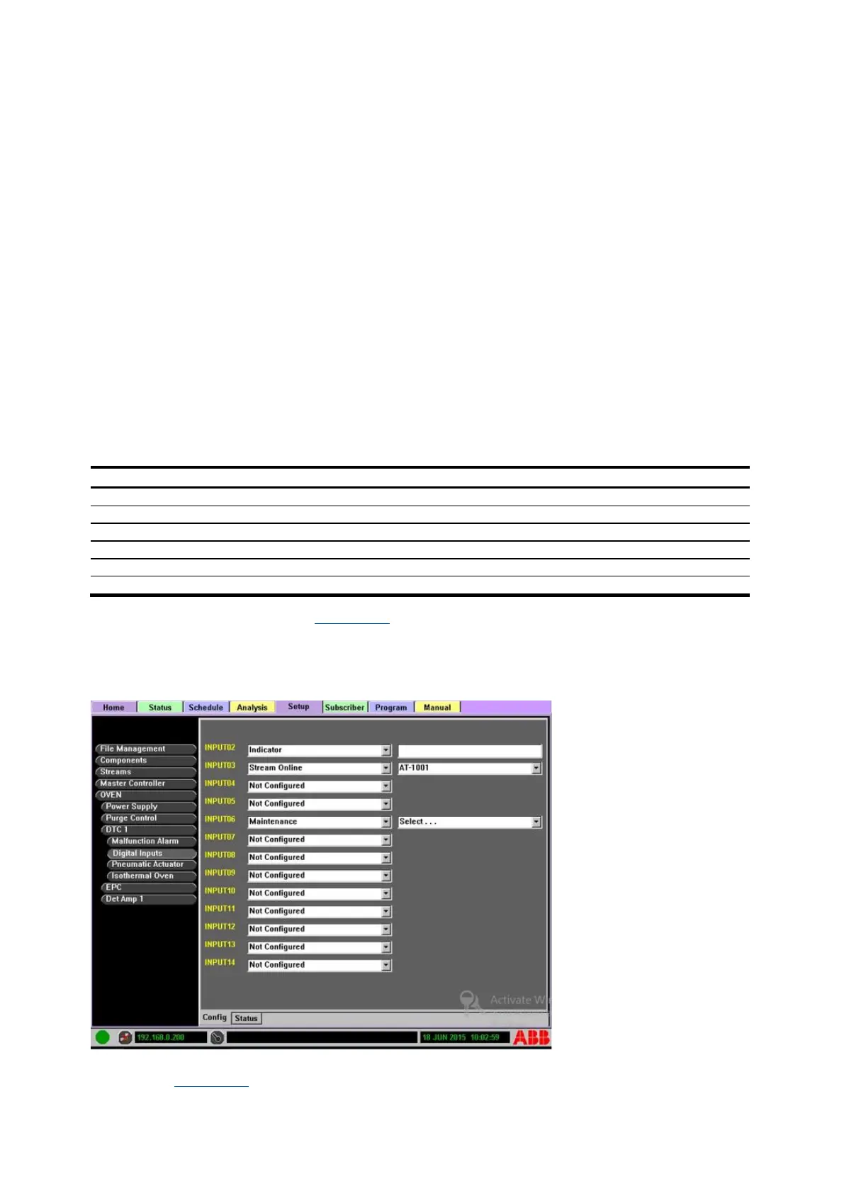
Configure digital inputs steps (see Figure 4-34):
1. Identify the digital input to configure.
2. Select DTC>Digital Inputs from the Function Select list.
3. Either enter text or select an option from drop-down list.
Figure 4-34: Set up Digital Inputs
⎯ Digital Input Status: The digital input status subtab displays the current state of the inputs
(see Figure 4-35). Some of the inputs are used for factory configuration.