892 J006 MNAH | PGC5000 G EN 2 | 75
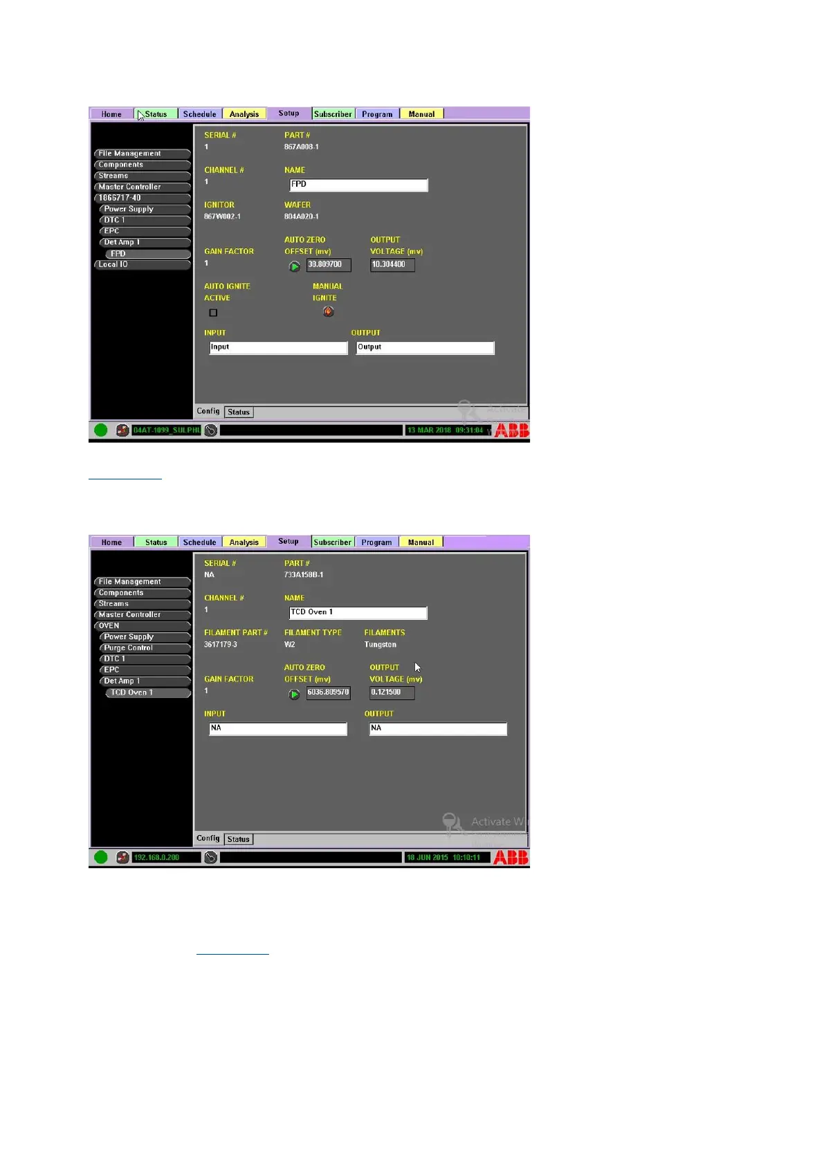
Figure 4-45: FPD configuration
The Oven> DetAmp> TCD> Configuration subtab displays the Serial, Part, and Channel number (see
Figure 4-46). It also displays the Filament Information, Gain factor and Output Voltage. A manual
AUTOZERO button is provided. You can also edit the input and output fields for easy reference from
this screen.
Figure 4-46: TCD configuration
4.7 Subscriber tab
The Subscriber tab allows the user to designate information collection points for the analyzer
information (see Figure 4-47). To automatically send analysis results and analyzer events to network
destinations, their addresses and names must be entered in the Subscriber Tab. Use the Subscriber
tab to edit the subscriber list from either the Master Controller’s front panel or PC-based RUI. The
Subscriber tab has two subtabs: Config and Modbus Map.