892 J006 MNAH | PGC5000 G EN 2 | 89
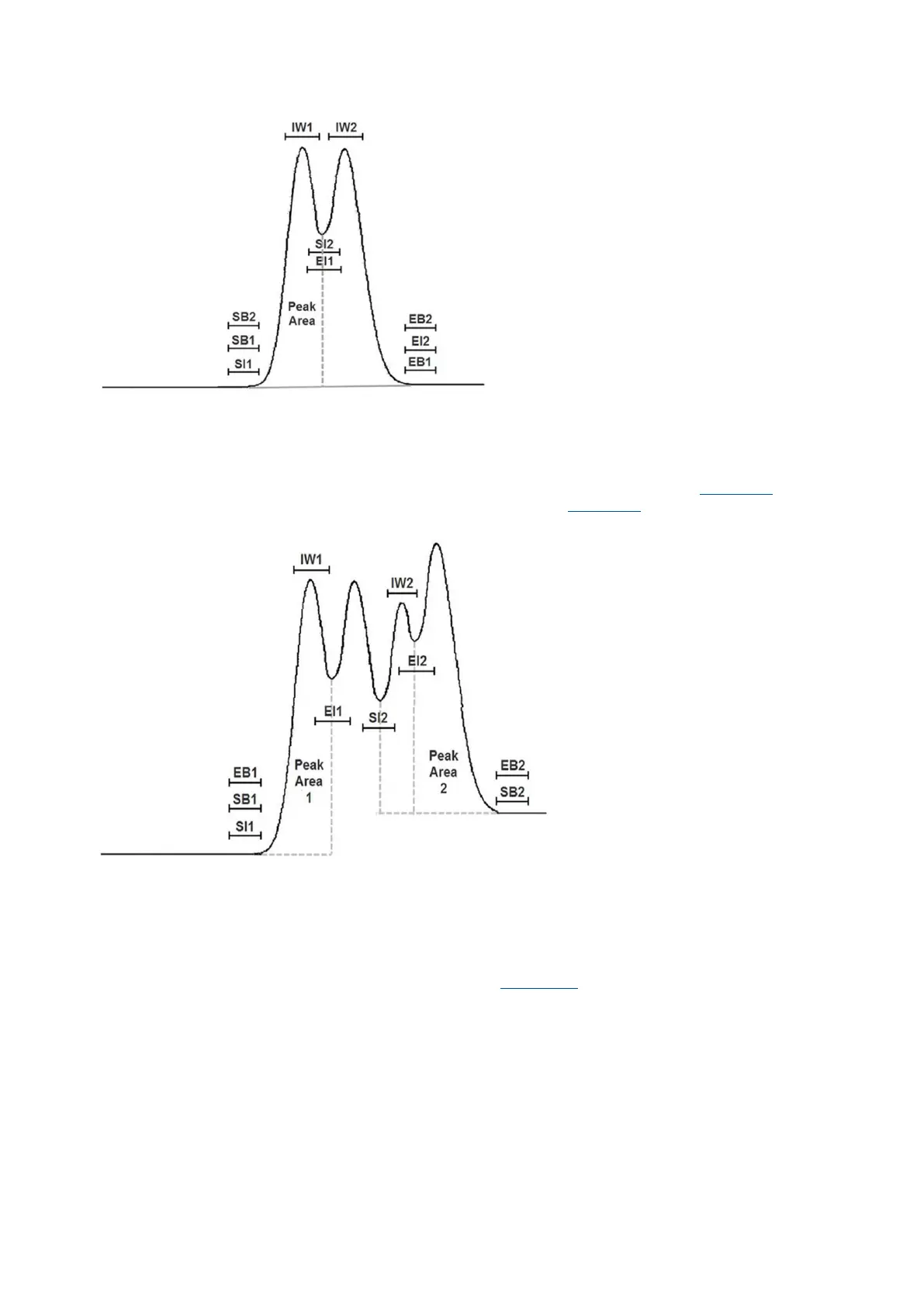
Figure 5-5: Min-max, separate peaks
5.3.4 Baseline correction, peak lumping
The min-max method completely defines the peak but requires careful placement of the windows to
cover all situations. The projection of a peak is used when either the SB or the EB are offset from each
other, or when no stable place can be found for one of them. A projection is accomplished by setting
SB and EB identically. If the windows occur before the IW, the projection is forward (Figure 5-6, peak
1). If the windows occur after the IW, the projection is backward (Figure 5-6, peak 2).
Figure 5-6: Baseline correction, peak lumping
5.3.5 Baseline correction, tangent skim
A small shoulder on a much larger peak is a tangent skimmed peak. The main peak extends beyond
the end of the skimmed peak where part of the area under the skimmed peak actually belongs to the
main peak. Treating the situation as two fused peaks would give an unreasonably large area to the
skimmed peak.
If the tangential skimmed peak were set up as shown in Figure 5-7, the standard baseline correction
of drawing a line between the SB and the EB would give the dashed line. This correction subtracts off
the area above the chromatogram and if this crescent-shaped segment becomes large enough, the
final peak area will go negative. Correct placement of the EB and the EI can avoid the problem, but
this is not always easily accomplished. Small movements of the tangential skimmed peak have a large
effect on the final peak area.