22 | PGC5000 GEN 2 | 892 J006 MNAH
A grounding (earthing) connection is required. Connect minimum 12 gauge (3.31 mm2) ground wire
to the Earthing Connection on the Oven Compartment and on the Master Controller.
WARNING – Bodily injury. The Neutral and Ground (earth) connections to the PGC5000
series Master Controller and B class oven must be at earth (0 volts) potential. Failure to
maintain earth (0 volts) potential at these connections points constitutes a serious safety
hazard.
2.6 Set up the Master Controller
The Master Controller (see
WARNING – Bodily injury. Failure to maintain earth (0 volts) potential at Neutral and Ground
connection points constitutes a serious safety hazard. There could be damage to equipment.
Figure 2-2) must be installed according to all applicable codes. If it will be in a hazardous area, the
wiring method must conform to the applicable requirements. General Master Controller connections
include:
⎯ Power wiring (circuit breaker protection must be supplied by the customer); refer to the
installation wiring drawing provided in the Data Package for details.
⎯ Signal fiber between the Master Controller and the Oven(s).
⎯ Alarm contact outputs; refer to the installation drawing in the Data Package for details.
⎯ Neutral and Ground (earth) connections must be at earth (0 volts) potential.
WARNING – Bodily injury. Failure to maintain earth (0 volts) potential at Neutral and Ground
connection points constitutes a serious safety hazard. There could be damage to equipment.
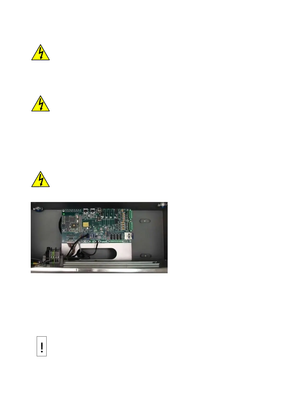
Figure 2-2: Inside the Master Controller
Refer to the applicable drawings in your Data Package for specific interconnection wiring information.
2.6.1 Single board computer PCB
The Master Controller and the Oven with Controller contain a Single Board Computer (SBC). The SBC
has built in redundant Ethernet Network Interface Connections (NICs) located at the top center of the
SBC, labeled J6 and J8. Note that Ethernet 1 is to the right and Ethernet 2 is to the left.
The SBC has an SBC CAN Interface Card for each oven, labeled 1 through 4 from left to right. This
module communicates with the oven via fiber optic cables attached to the board by two connectors.
The fiber optic cables utilize two type ST connectors. The customer is required to install all fiber optic
connections.
NOTICE – Equipment damage. Sharp bends in a fiber optic cable can cause signal
attenuation or the optical fiber to break.