ADPRO FastTrace by Xtralis Installation and User Manual
Doc 11168_12 19
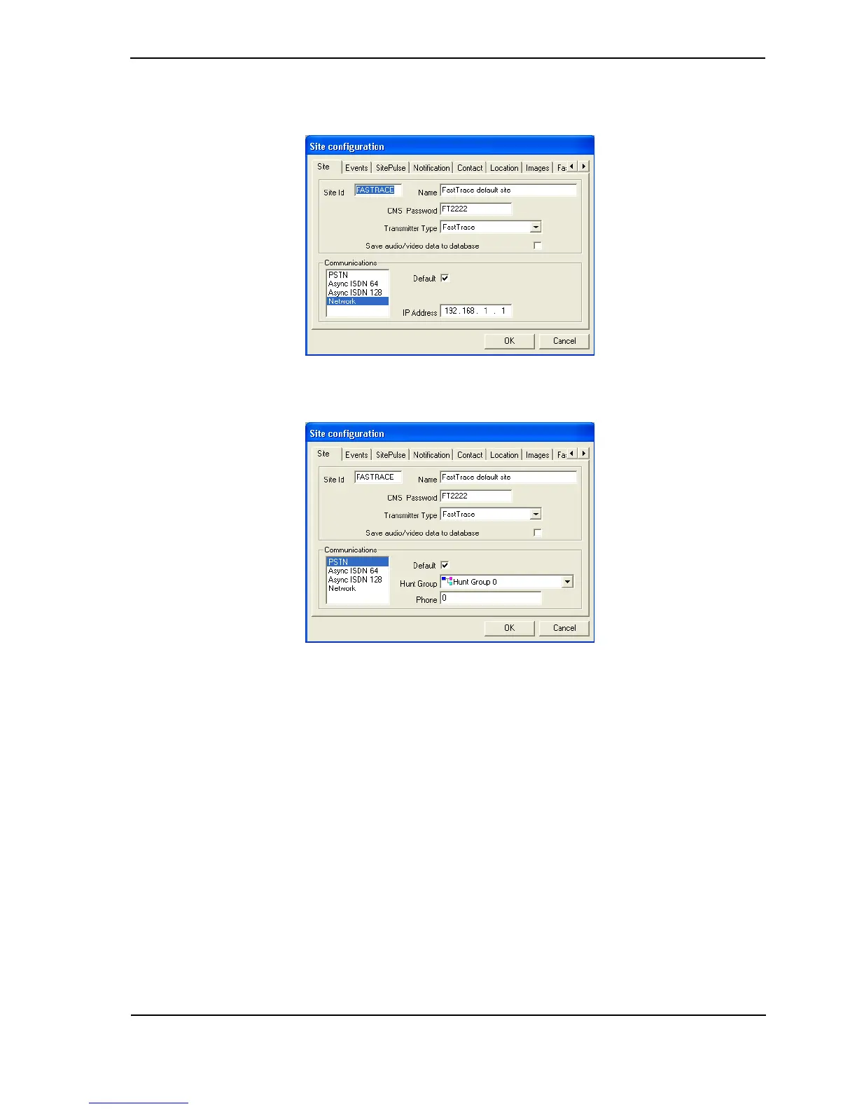
3. To check the defaults, select the FastTrace default site entry and click Edit. The Site
Configuration details are shown with the default values, as follows:
Figure 23: Default Ethernet Site Configuration
Figure 24: Default Serial Site Configuration
2.8 FastTrace Configuration
1. Before powering the FastTrace unit on, check that the factory DIP-Switch settings are
correct (refer to Table 7 on page 38 for more details).
The location of the DIP-Switch is on the rear of the FastTrace unit at the bottom, underneath
the camera connections and next to the monitor connector.
2. Set the DIP-Switch 10 to the appropriate video standard for the region:
- (ON - NTSC, OFF - PAL).
3. Ensure the airflow vents into the side of the FastTrace unit are not blocked.
4. Connect the crossover Ethernet cable between the FastTrace Ethernet port and the PC’s
Ethernet port or the null modem cable between the Comm2 port and the PC’s serial comms
port.
5. Once DIP-Switch settings are verified and all cables are connected, plug in the mains
power cable.