Installation and User Manual ADPRO FastTrace by Xtralis
86 Doc 11168_12
The Live option is primarily designed for use with access (entry/exit) points. A live video feed is
displayed at VideoCentral.
The Quad option captures three alarm images in a user-defined period (defined under Camera
Settings/General tab) and displays the images at VideoCentral, along with a fourth pane which
sequences through the three images to highlight movement.
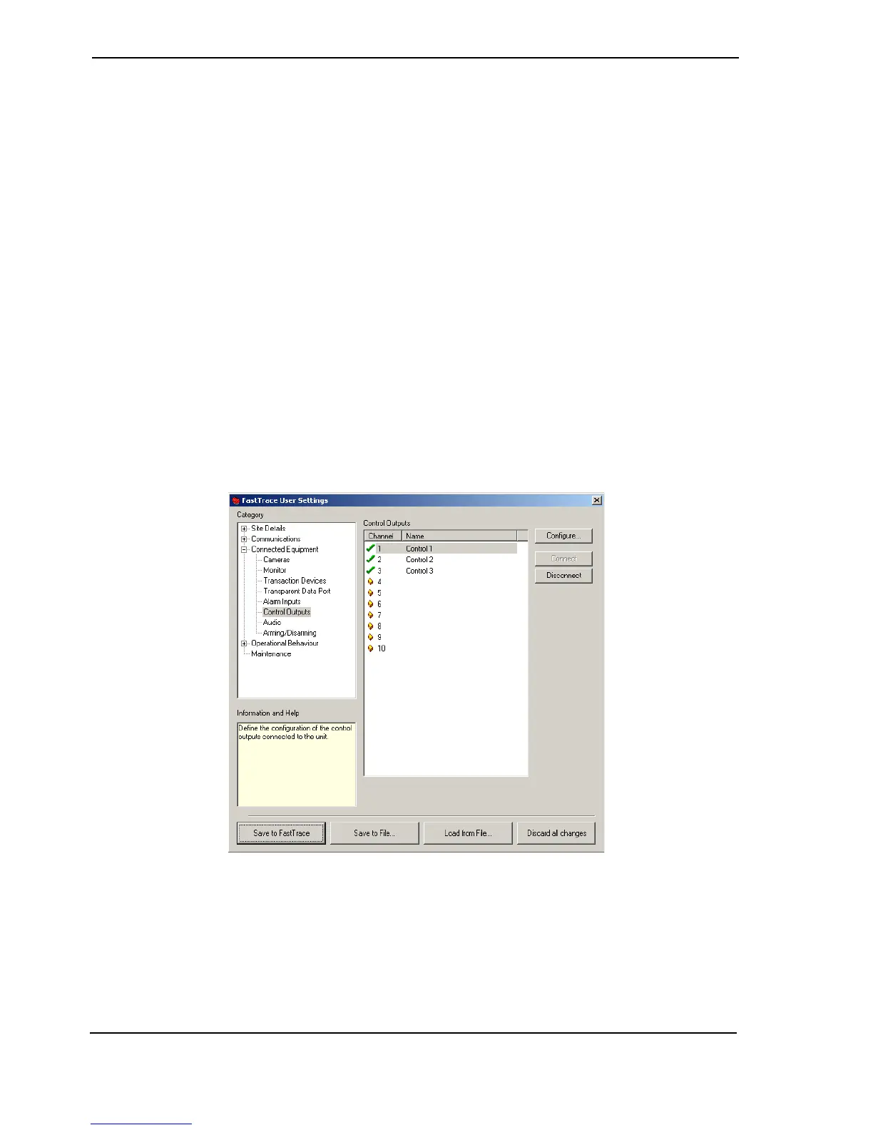
4.3.15 Control Outputs
The Control Outputs option defines a number of parameters about the type and operation of the
output circuits connected to the FastTrace. The outputs are ‘open collector’ transistor circuits
used to generate a control signal (upon activation of an alarm) to activate third-party equipment
at the remote site, for example a boom gate controller or a floodlight control device.
Select the control output number from the displayed list. The number of control outputs available
depends on the FastTrace Model number. The status of a control output is shown by a small icon
to the left of the channel number.
• A control output is free when the ‘empty’ icon is shown next to the number
•The Connect button is used to enable a control output. A green tick is shown and details
can be modified
• To temporarily disable the use of a control output, the Disconnect button is used and a red
cross is shown. For example, set Disconnect if maintenance is being performed on the unit
under control.
Figure 85: Control Output Settings Menu