ADPRO FastTrace by Xtralis Installation and User Manual
Doc 11168_12 43
3.8.1 Connecting to the Control Outputs
Control Outputs are available via screw connection strips on the rear panel.
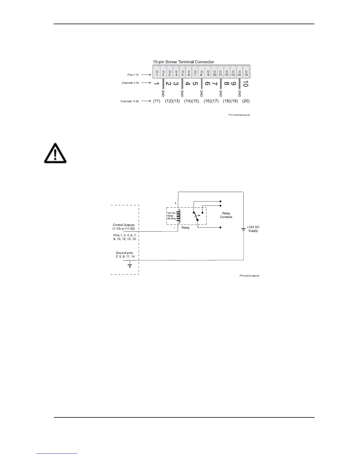
Figure 45: Pinouts for Control Output Connectors
Caution: Exceeding the Control Output’s maximum voltage or current rating
(12 Vdc, 100 mA) will damage the FastTrace and invalidate the product warranty.
For high power/voltage equipment, suitable interface circuitry must be used
between the Control Outputs and the equipment.
A typical output circuit for an external relay is shown below:
Figure 46: External Relay - Typical Output Circuit
3.9 PTZ Connection
Telemetry stations are used for the control of cameras with Pan/Tilt/Zoom (PTZ) hardware. They
are connected to the FastTrace and can be controlled by commands issued via the PTZ port
connector.
FastTrace supports a number of PTZ telemetry station models provided all of the PTZ units are
the same model. Communications with the telemetry stations utilises RS485 ‘multi-drop’
signalling via the ‘PTZ’ port on the rear of the chassis.
FastTrace supports ‘Down the Coax’ telemetry. A ‘Down the Coax’ telemetry module must be
installed in the FastTrace if this functionality is required. Please contact your service centre if this
option is required.