ADPRO FastTrace by Xtralis Installation and User Manual
Doc 11168_12 45
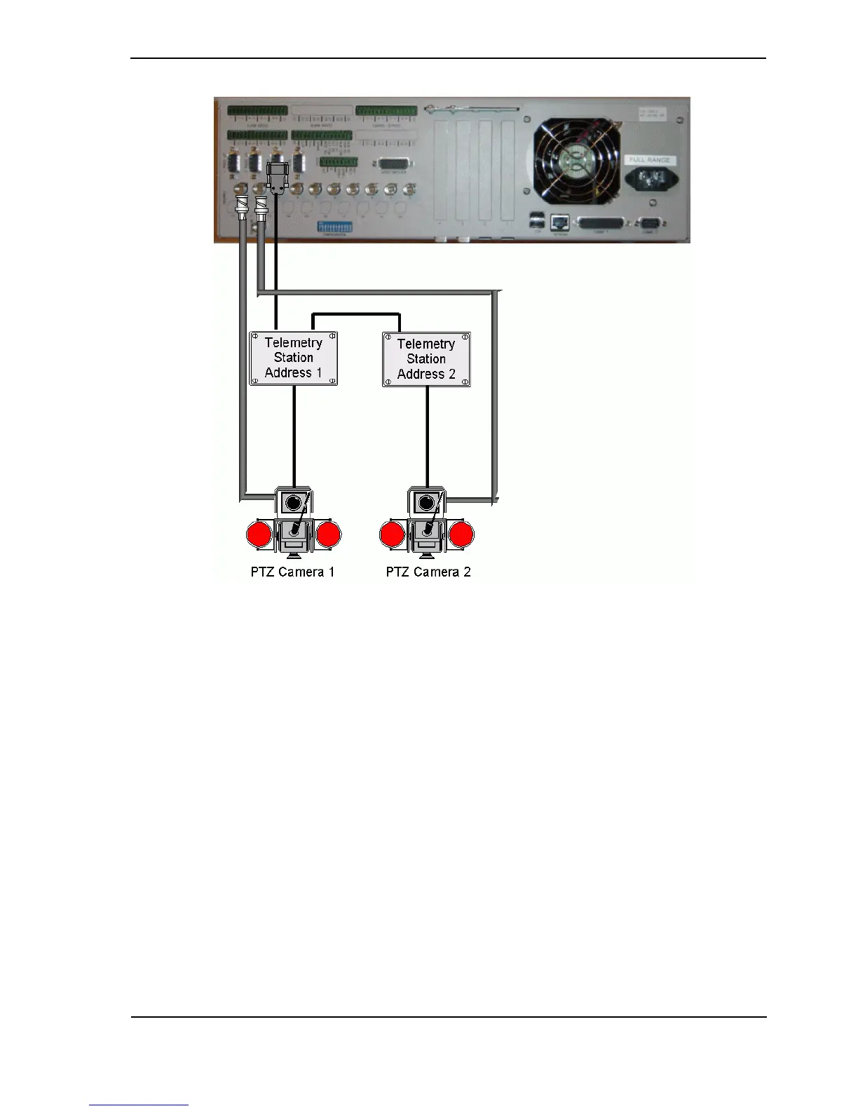
Figure 49: Typical PTZ Configuration
3.9.1 PTZ Port Setup
The following points are applicable to the PTZ port.
• Telemetry stations are connected via a 9-pin D connector, marked ‘PTZ’
• RS485 control links allow cable lengths of up to 1000 metres
• Up to 20 (identical) telemetry stations can be connected to one FastTrace
Use the following guidelines when connecting and setting up a telemetry station.
• The same brand and model of telemetry station must be used at a site if multiple units are to
be used.
• Set the address of the telemetry station to match the camera input to which the PTZ camera
is connected.
• Use shielded twisted pair cable for connection to the telemetry stations.
• Connect the Transmit positive (TXD+ pin#2), Transmit negative (TXD- pin#3) and Ground
terminal (pin#5) of the FastTrace PTZ connector to the respective positive, negative and
ground terminals of the telemetry station as shown below.