Installation and User Manual ADPRO FastTrace by Xtralis
48 Doc 11168_12
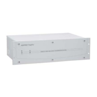
Figure 53: Pin Numbering of the Data Port
Table 10: Data Port Connections
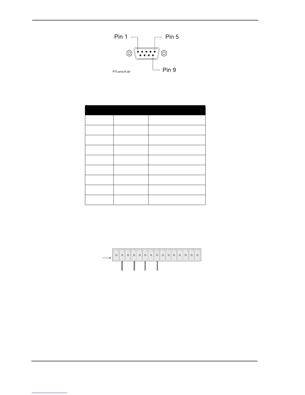
3.12 Connecting to the General I/O
General Inputs/Outputs are available via screw connection strips on the rear panel.
Figure 54: Pinouts for General I/O Connector
3.12.1 Export Evidence - Pin 1
Currently not used.
PIN Signal Description
1 DCD Carrier Detect
2 RXD Receive Data
3TXDTransmit Data
4 DTR Data Terminal Ready
5 GND Signal Ground
6 DSR Data Set Ready
7 RTS Request to send
8 CTS Clear to send
9 +V Signal High