U511 User’s Manual Parameters
Version 1.1 Aerotech, Inc. 4-87
4.11.4. “MFO pot offset” (0-255)
This parameter is used to enable or disable an optional manual feed override (MFO)
potentiometer (pot). The MFO pot, if used, is attached to the auxiliary I/O connector on
the rear of the chassis of the UNIDEX 511.
The “MFO pot offset” parameter has a range from 0 to 255. A value of 0 should be used
if the MFO option is not used. A 0 value can also be used to disable an existing MFO
pot. If an MFO pot is enabled (that is, parameter 002>0), then the value set by this
parameter represents an offset that becomes the new 0% MFO position. Refer to
Table 4-64.
Table 4-64. Settings for Parameter 002
Value Description
0 Used when the MFO potentiometer option is not being used or to
disable an existing MFO pot. (default)
1-255 Specifies the “MFO pot offset” for 0% MFO.
If the pot is enabled (i.e., parameter 002>0), the U511 reads the current pot position (as a
value from 0 to 255 counts) through an 8 bit A/D converter. The value of parameter 002
shifts the 0% MFO mark, thereby creating a user-definable low-end deadband over which
the MFO is 0%. The new MFO percentage is then defined as a function of the MFO
offset from parameter 002 (a value from 1-255) and the actual A/D converter value (0-
255) read by the U511. Setting parameter 002>0, effectively creates a low-end pot
deadband and automatically rescales the remainder of the pot range over the remaining
number of converter counts. This is accomplished using the following equation.
MFO % = (( 1 + Converter Value - Value of Parameter 002) / 255 ) * 100%
For example, setting parameter 002 = 55 will create a 55-count deadband at the low end
of the pot range. The A/D converter data from 0 to 55 counts will be treated as a 0%
MFO. Any data greater than 55 can be calculated by substituting the current A/D
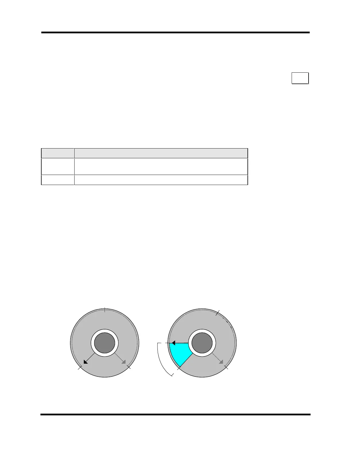
converter value (56-255) in the above equation and solving for MFO %. See Figure 4-13.
The typical value for this parameter when connecting to a pot is 10.
0%
199%
0%
100% MFO
199%
100% MFO
Parameter 002=1
Parameter 002=55
(0)(255)
(0)
(255)
(5)5
(182 c
1c(8n)2ts
nts)
Figure 4-13. MFO Potentiometer With and Without Offsets
002
Artisan Technology Group - Quality Instrumentation ... Guaranteed | (888) 88-SOURCE | www.artisantg.com

 Loading...