U511 User’s Manual Appendix G
Version 1.1 Aerotech, Inc. G-11
G.7. Nulling the Phase Offset (Rotary Inductosyns Only)
To null the phase offset of rotary Inductosyns, perform the following.
1. Disable the axis being tested.
2. Set the appropriate converter demodulator adjust mode jumper (JP1 through JP4) for
the axis being tested to the “enabled” configuration.
3. Connect an O-scope to pin #1 of the appropriate RCN# (where RCN1 = Axis #1,
RCN2 = Axis #2, etc.). For example, if checking Axis #1, then connect the O-scope
to pin #1 of RCN1. Connect the ground lead to TP4.
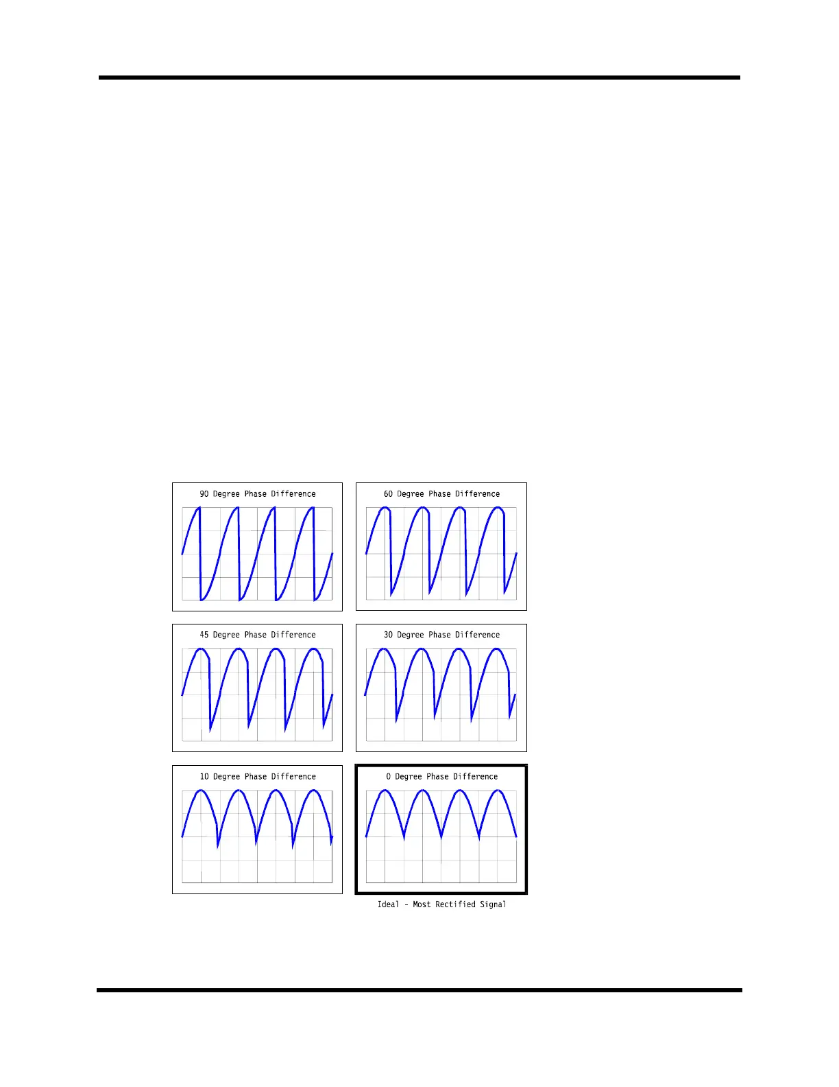
4. Adjust the phase offset pot (R1) until the ideal rectified signal is present. Refer to
Figure G-5. Get as close as possible.
• A different capacitor may be needed for pins 5 and 10 of RCN5
• The R1 pot adjusts the phase offsets for all 4 axes (only applies if they are rotary
Inductosyns), so if more than one rotary Inductosyn is being used, they have to
be of the same type
5. Return the previously set jumper (JP1 through JP4) to the “disabled” configuration.
Figure G-5. Rectified Signals with the Most Ideal Signal
Artisan Technology Group - Quality Instrumentation ... Guaranteed | (888) 88-SOURCE | www.artisantg.com

 Loading...