U511 User’s Manual Technical Details
Version 1.1 Aerotech, Inc. 10-19
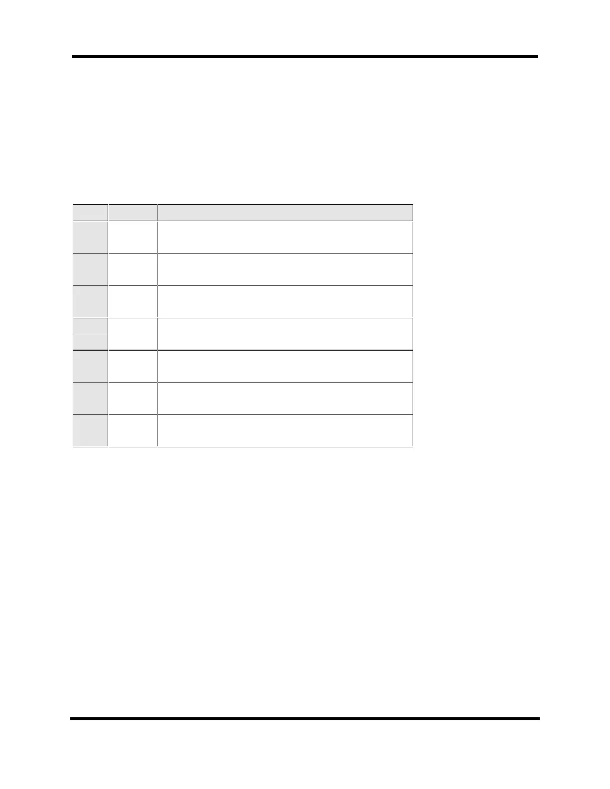
10.3. Interface Board Jumpers
Table 10-15 describes the U511 Interface Board “JP” jumpers. The user can change
jumpers 1-6. Refer to Figure 10-9. The other jumpers are factory configured and should
not be changed by the user.
Table 10-15. Interface Board jumper “JP” description (JP1-JP46)
JP # Setting Description
1 1-2*
2-3
COM 1: J7-2 data out ( for direct connection to PC )
COM 1: J7-2 data in
2 1-2*
2-3
COM 1: J7-3 data in ( for direct connection to PC )
COM 1: J7-3 data out
3 IN*
OUT
COM 1: RTS (J7-7) connected to CTS (J7-8)
COM 1: RTS (J7-7) not connected to CTS (J7-8)
4 1-2*
2-3
COM 2: J8-3 data in ( for direct connection to PC )
COM 2: J8-3 data out
5 1-2*
2-3
COM 2: J8-2 data out ( for direct connection to PC )
COM 2: J8-2 data in
6 IN*
OUT
COM 2: RTS (J8-7) connected to CTS (J8-8)
COM 2: RTS (J8-7) not connected to CTS (J8-8)
7-46 Reserved - factory configured
( refer to Engineering Specification )
* Default Setting
Artisan Technology Group - Quality Instrumentation ... Guaranteed | (888) 88-SOURCE | www.artisantg.com