The User Interface U511 User’s Manual
3-22 Aerotech, Inc. Version 1.1
Table 3-2. Primary I/O Status Diagnostics
Field Status Description
Inputs Shows inputs on the 16 IN/8 OUT bus (0 = GND level, 1 = +5 V
level).
Outputs Shows outputs on the 16 IN/8 OUT bus. A 0/1 on the output
corresponds to the programmed output level.
A/D inputs 1-4 Shows the direct analog/digital converter voltage (0-5 V) for the
corresponding input.
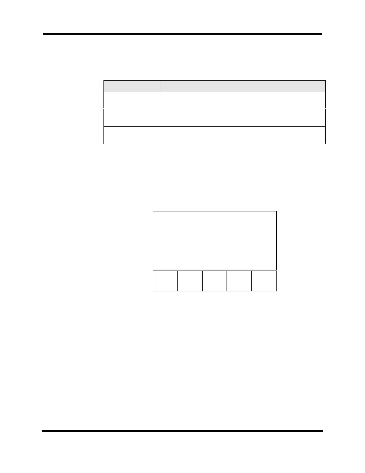
3.6.3. Diagnostics Menu: System Status Page
The System Status page (Page 3) displays the manual feed override (MFO) value,
Emergency Stop status, Brake status, Pause status, Joystick status, and the Status Word.
The System Status page is shown in Figure 3-25. Table 3-3 describes the components of
the System Status page.
F1 F2
F5
Page 3 Sy
MFO 100.0%
Emergency Stop N
Brake Y
Pause N
Joystick ABC HHH
Status Word 00000F
Back Next Quit
Figure 3-25. System Status Page
Artisan Technology Group - Quality Instrumentation ... Guaranteed | (888) 88-SOURCE | www.artisantg.com