U511 User’s Manual The User Interface
Version 1.1 Aerotech, Inc. 3-23
Table 3-3. System Status Diagnostics
Field Status Description
MFO Shows the current manual feed override percentage from 0% to
199%. Also displayed in the MDI window if not equal to 100%.
Emergency Stop Indicates current E-Stop status (Y = on, N = off) if E-Stop bit in
any fault mask is enabled and E-Stop input is true. Also shown in
the MDI window.
Brake Indicates brake status (Y = on, N = off). The brake is a U511
option requiring additional hardware and is enabled in the fault
mask.
Pause Indicates pause status (Y = pause, N = no pause). Pressing the
PAUSE button on the front panel toggles the pause state.
Joystick ABC Indicates current functionality of the joystick buttons. A, B, and C
do not physically correspond to the joystick buttons. The C on the
screen is the interlock signal that must be low (L) for the joystick
to operate. A and B correspond to the joystick “A” and “B”
buttons. Pressing joystick “A” or “B” buttons causes the display
to go from H to L. The joystick “C” button activates both “A” and
“B” buttons/status bits.
Status Word Indicates the internal “read status (5)” value.
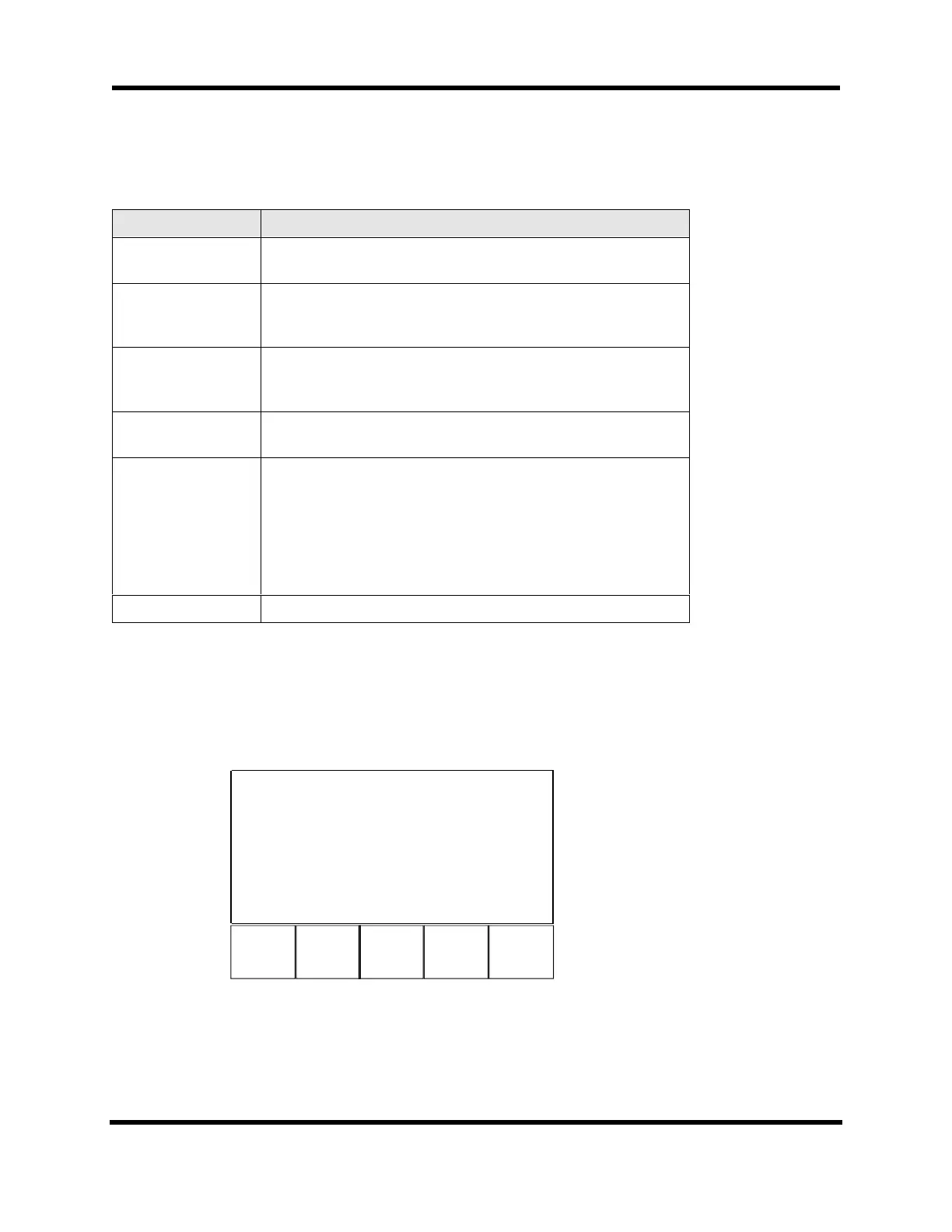
3.6.4. Diagnostics Menu: Position Page
The Position page (refer to Figure 3-26) displays In Position status, Marker status, and the
individual Axis Positions. Table 3-4 shows components of the Position page.
F1 F2 F3 F4
Page 4 Position 1 2
4
In Position * *
*
Marker * -
-
Axis 1 Position [0000] 0
Axis 2 Position [2000] 0
Axis 3 Position [0000] 0
Axis 4 Position [0000] 0
Back Next Q
t
Figure 3-26. The Position Page
Artisan Technology Group - Quality Instrumentation ... Guaranteed | (888) 88-SOURCE | www.artisantg.com