Technical Details U511 User’s Manual
10-12 Aerotech, Inc. Version 1.1
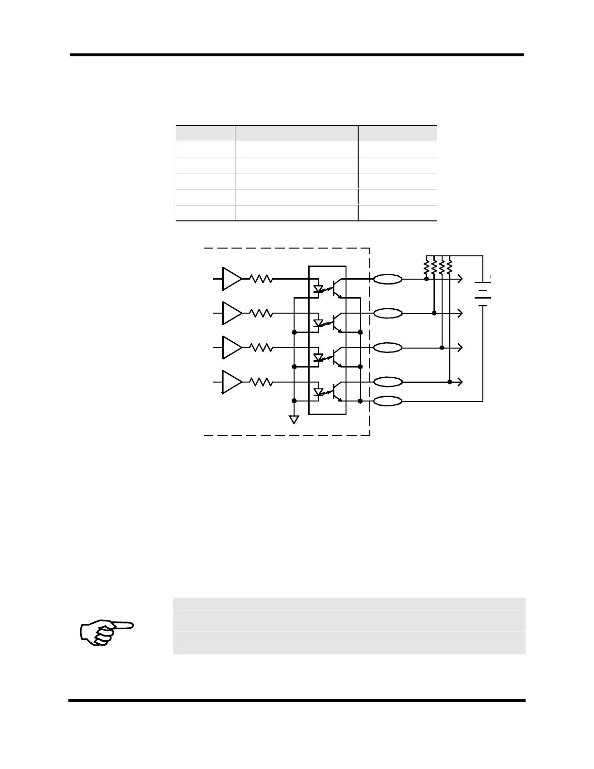
Table 10-8. Opto-isolated Output Pin Locations
Name Description AUX I/O pin#
IOUT0 Isolated output 0 19
IOUT1 Isolated output 1 20
IOUT2 Isolated output 2 21
IOUT3 Isolated output 3 22
IOUTCOM Common point of emitters 23
OPTO ISOLATED OUTPUTS
PS 2501
AUX I/O
CONNECTOR
19
20
21
22
23
IOUT0
IOUT1
IOUT2
IOUT3
IOUT COM
Figure 10-5. Opto-Isolated Outputs
10.1.4. AUX I/O Connector
The AUX I/O connector contains miscellaneous I/O signals for the U511. These include
the hardware interrupt, (UINT), emergency stop input (E-Stop), 4 in/4 out opto isolated
I/O and associated power supply connections, D/A outputs (shared by amplifiers), and
analog inputs.
Table 10-9 shows the pinouts for the AUX I/O connector. The mating connector is a
Cinch # DC-37P (Aerotech # ECK00119).
DAC channels are used as current commands to the internal amplifiers. Unused DAC
channels are available for general purpose use. AC brushless and Stepper motors
require two DAC channels; DC motors require only 1.
UNIDEX 511
Artisan Technology Group - Quality Instrumentation ... Guaranteed | (888) 88-SOURCE | www.artisantg.com