Appendix
U511 User’s Manual
G-8 Aerotech, Inc. Version 1.1
G.5. Connecting the Device to the RDP Board
Resolvers or Inductosyns connect to the RDP-PC through P1 on the back of the RDP-PC
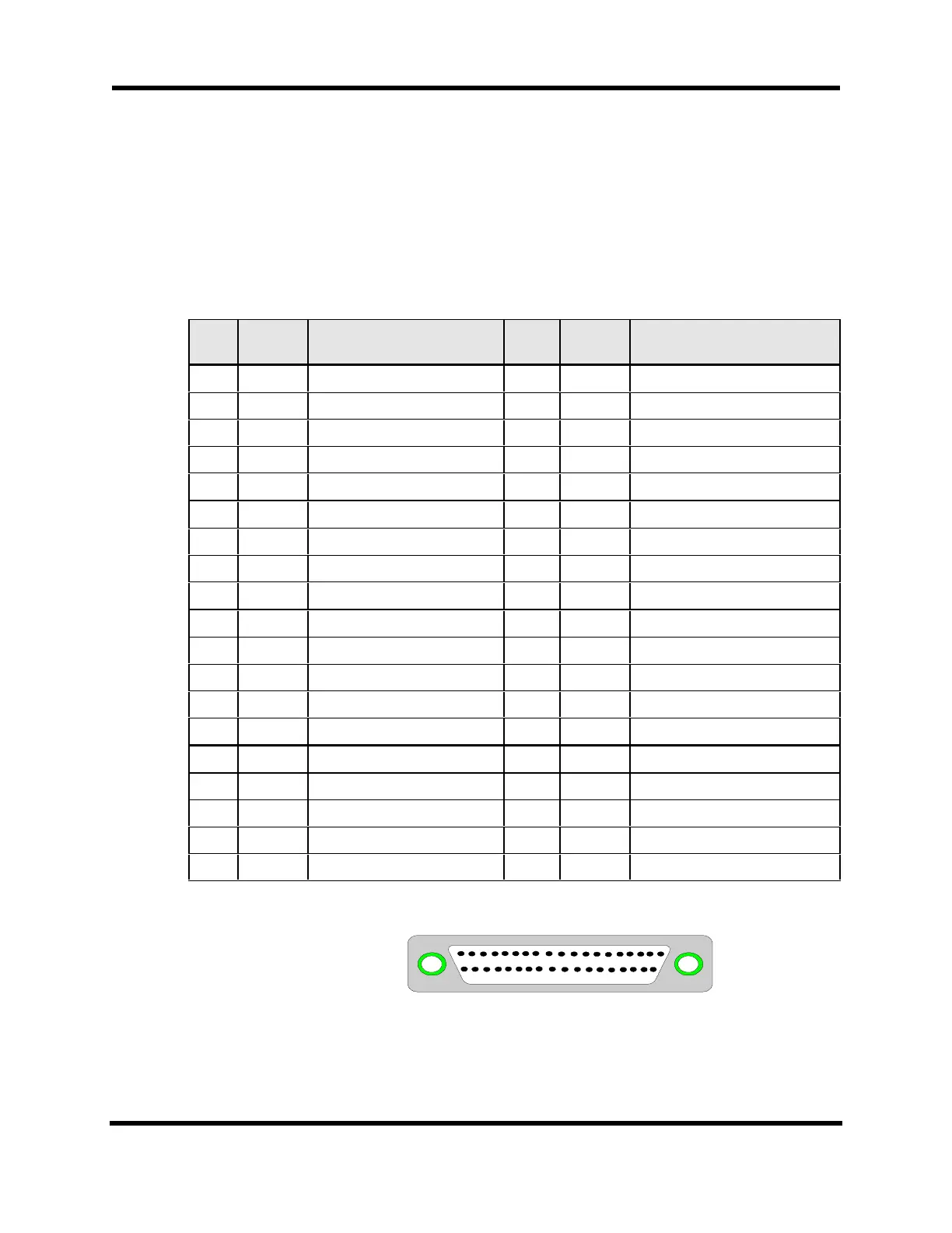
board. The pinouts for the connector are listed in Table G-10. Figure G-3 shows the
mating DB37 connector while Figure G-4 shows the suggested cabling between the RDP
board and a resolver or Inductosyn.
Table G-10. RDP Board Pinouts
Pin
#
Axis # Signal Pin
#
Axis # Signal
1 4 Shield 20 4 COS -
2 4 COS + 21 4 SIN -
34 SIN + 22–– Ground
4 4 Ground 23 4 Over-temp thermistor input
5 4 REF + 24 –– Ground
6 3 REF + 25 3 Over-temp thermistor input
7 3 Shield 26 3 Ground
8 3 COS + 27 3 COS -
9 3 SIN + 28 3 SIN -
10 2 Over-temp thermistor input 29 –– Ground
11 2 REF + 30 2 Ground
12 2 Shield 31 –– Ground
13 2 COS + 32 2 COS -
14 2 SIN + 33 2 SIN -
15 1 Over-temp thermistor input 34 –– Ground
16 1 REF + 35 1 Ground
17 1 Shield 36 1 COS -
18 1 COS + 37 1 SIN -
19 1 SIN +
1 19
20 37
Figure G-3. Mating DB37 Connector
Artisan Technology Group - Quality Instrumentation ... Guaranteed | (888) 88-SOURCE | www.artisantg.com


 To Next Page