The User Interface U511 User’s Manual
3-26 Aerotech, Inc. Version 1.1
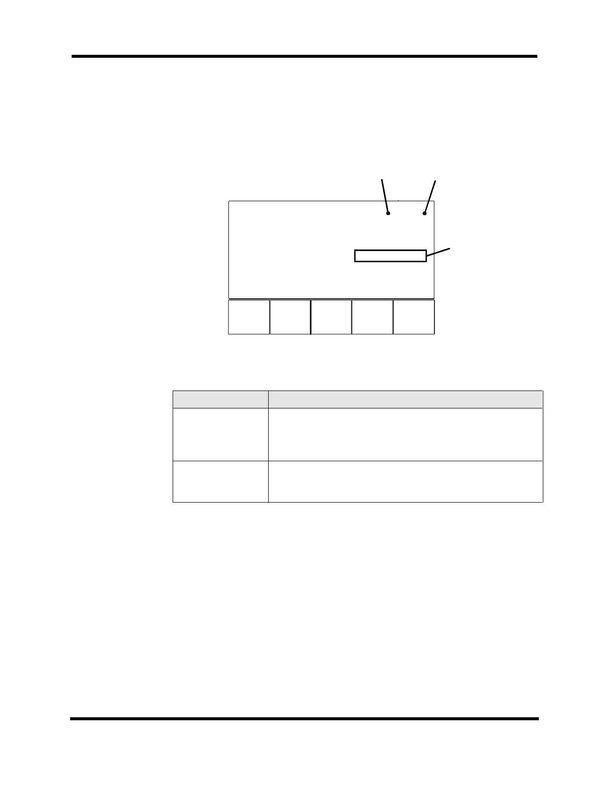
3.6.7. Diagnostics Menu: Secondary I/O Page
The Secondary I/O page (refer to Figure 3-29) displays the status of the 8 X 3 I/O bus and
the Hall inputs. Components of the Secondary I/O page are shown Table 3-7.
F1 F2 F3
Page 7 Secondary I/O
I/O bank A 0000000
I/O bank B 000000
I/O bank C 000000
432
Hall Inputs CAB 101 101 101
Back Next Qu
Axis No.
LSBM
Figure 3-29. Secondary I/O Page
Table 3-7. Secondary I/O Diagnostics
Field Status Description
I/O banks A-C Shows the current input status of the 8 X 3 I/O bus if programmed
as inputs. When configured as outputs, shows the programmed
output value. See the IOSET and IO commands in Chapter 5:
Programming Commands.
Hall Inputs CAB Applicable only with AC brushless motors. Indicates the state of
the Hall sensors. See Motor Setup (MSET) command in Chapter
5: Programming Commands.
3.6.8. Diagnostics Menu: Terminal Page
The Terminal page (refer to Figure 3-30) monitors serial and GPIB communications
between the U511 and a host system. This page may also be used to send characters. To
select the port to transmit to, press the up or down arrows. The selected port will have an
underline cursor (_). Other ports will have a solid block cursor. Type from the keyboard
or input from the front panel. These characters will be transmitted to the host system. An
“*” beside the port indicates that remote communications are active on that port. The
active components of the Terminal page are shown in Table 3-8.
Artisan Technology Group - Quality Instrumentation ... Guaranteed | (888) 88-SOURCE | www.artisantg.com