Tuning Servo Loops U511 User’s Manual
8-14 Aerotech, Inc. Version 1.1
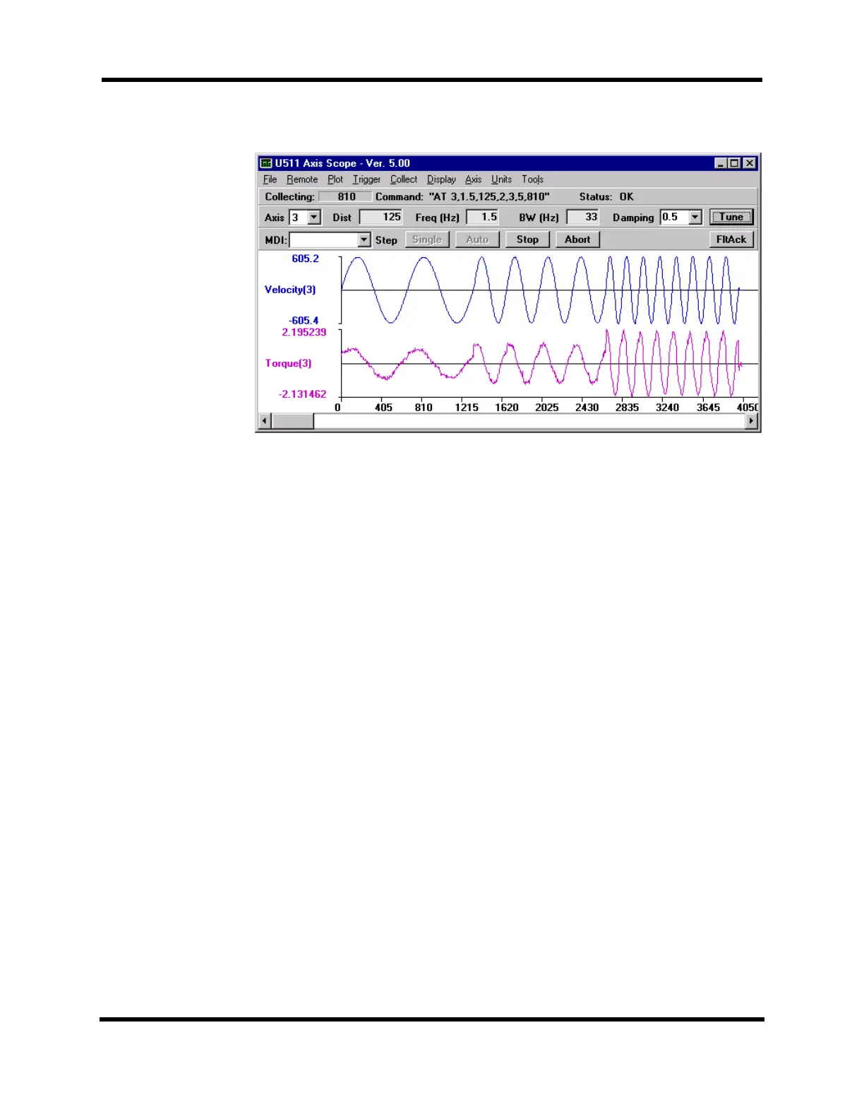
Figure 8-8. Autotune Plot Showing Proper Calibration
8.4.5. Dual Loop Systems
Autotuning may be performed on dual loop systems by temporarily configuring the U511
to run in single loop mode, i.e. from the velocity feedback transducer only. This is
accomplished by setting the primary feedback channel parameter (axis parameter x38) to
the velocity feedback device’s channel and setting the secondary feedback channel (axis
parameter x39) to 0. Autotuning will yield the correct values for Ki and Kp. The Kpos
term will need to be manually adjusted when the U511 configuration is returned to dual
loop mode.
8.4.6. Guidelines and Limitations
• It is usually necessary to defeat the velocity error and position error traps before
tuning.
• If you do not have ballpark gains for a system, start out with low values, Kpos=10,
Ki=1000, Kp=10,000.
• Most systems should be able to achieve a bandwidth of at least 30Hz.
• Care must be taken not to exceed the maximum tracking rate of the feedback device,
especially resolvers/inductosyns. Large gimbals with inductosyns cannot use
autotuning.
• Autotuning will work with vertical axis configurations.
• For systems with large mass or high inertia, it may be necessary to reduce the
excitation frequency to .25 - .5Hz. For small systems, it may be necessary to increase
the frequency to 2Hz.
• Autotuning can be run on unconnected motors and linear motors.
Artisan Technology Group - Quality Instrumentation ... Guaranteed | (888) 88-SOURCE | www.artisantg.com