U511 User’s Manual Parameters
Version 1.1 Aerotech, Inc. 4-23
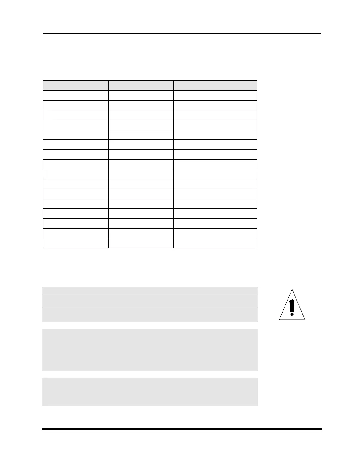
Table 4-15. Sample Calibration Table
Displayed Distance Actual Distance Correction Data
1000 1001 +1
2000 2002 +2
3000 3003 +3
4000 4005 +5
5000 5007 +7
6000 6009 +9
7000 7012 +12
8000 8014 +14
9000 9016 +16
10000 10014 +14
11000 11010 +10
12000 12008 +8
13000 13005 +5
14000 14002 +2
15000 15001 +1
16000 16000 0
The calibration (.CAL) file can also contain axis orthogonality correction data. This is
similar to axis calibration. Refer to Figure 4-2.
For orthogonality correction, axis correction will not begin until the position
dependent axis completes a home cycle and axis parameter x71 of the position
dependent axis (“Enable orthogonality table” parameter[x71]) is set to “yes.”
It is conceivable that a single calibration (.CAL) file might contain eight sections:
four axis calibration sections and four orthogonality correction sections. Axis
calibration and orthogonality correction may be enable/disabled independently
using parameters x15 and x71 as appropriate.
The corrected axis position (in machine steps) can be observed in the Diagnostics
window.
IMPORTANT
E
E
Artisan Technology Group - Quality Instrumentation ... Guaranteed | (888) 88-SOURCE | www.artisantg.com