U511 User’s Manual Getting Started
Version 1.1 Aerotech, Inc. 2-3
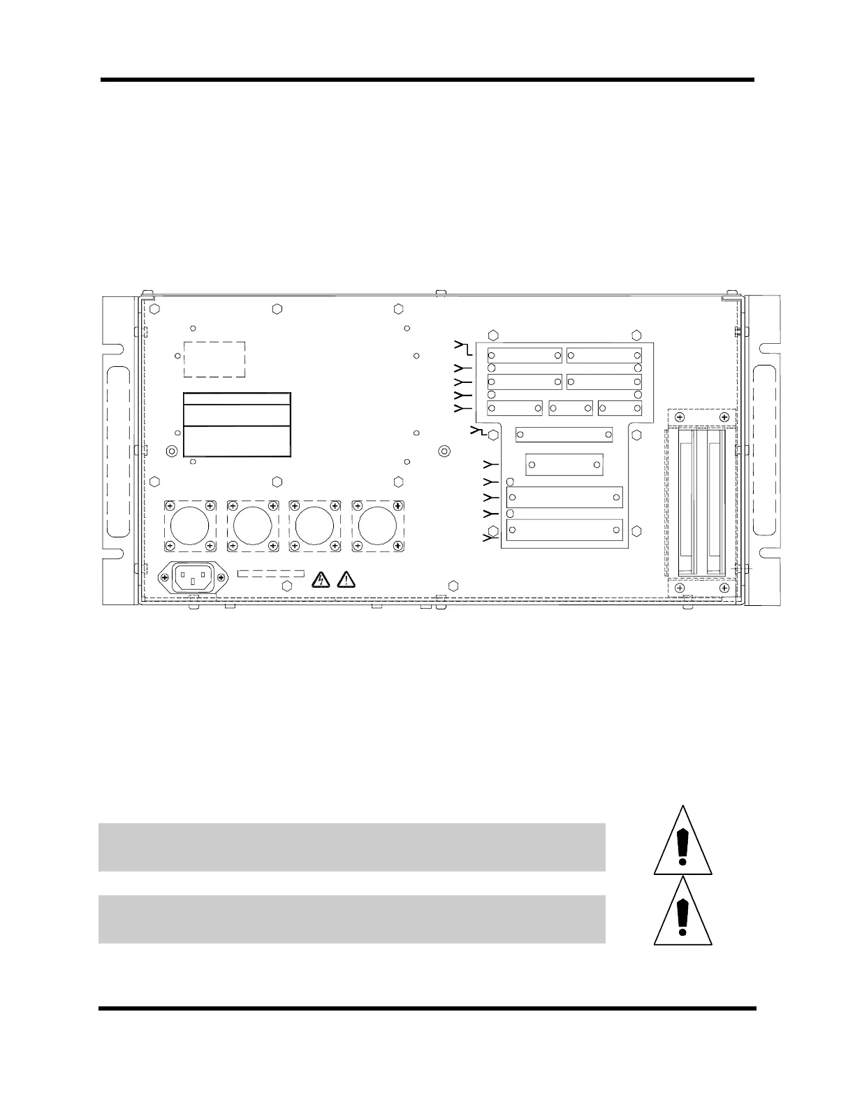
2.4. Installing Cables and Wiring
System installation varies with the number and types of components that have been
purchased from Aerotech, Inc. to complement the UNIDEX 511 PC bus controller. The
following descriptions may not be applicable to all systems. Figure 2-2 is an illustration
of the rear panel connectors.
DS3
DS2
25 1
50 26
25 1
50 26
(left) Encoder Input 1 (right) Encoder Input 2
(left) Encoder 1, 5V OK (right) Encoder 2, 5V OK
(left) Encoder Input 3 (right) Encoder Input 4
(left) Encoder 3, 5V OK (right) Encoder 4, 5V OK
(left) Joystick Interface (center) Communications Port 1
(right) Communications Port 2
13 1 13 1
25 14 25 14
13 1 13 1
25 14 25 14
8 1 5 1 5 1
15 9 9 6 9 6
J2
AXIS 1
J4
AXIS 3
J3
AXIS 2
J5
AXIS 4
J6
JOYSTICK
J7
COM 1
J8
COM 2
J12
8 X 3 I/O BUS
J11
16IN/8OUT
J10
AUX. I/O
J9
IEEE 488/GPIB
19 1
37 20
12 1
24 13
DS7 DS5
DS6 DS4
Opto I/O, User Interrupt, Brake, Emergency Stop,
And Analog I/O
IEEE 488/GPIB Interface
16 In/8 OUT 5V OK
16 IN/8 OUT Digital I/O to
OPTO 22 PB8, PB16, PB24
8 x 3 I/O Bus 5V OK
8 x 3 I/O Bus to OPTO
22 PB8, PB16, PB24
J23 J22 J21 J20
AXIS 4 AXIS 3 AXIS 2 AXIS 1
AC TAG
Serial Ta
AEROTECH
World Headquarters:
101 Zeta Drive
Pittsburgh, PA 15238 USA
USA: (412) 963-7470 Sales FAX: (412) 963-7459
USA Service FAX: (412) 963-7009
UK: 0734-817274 FAX: 0734-815022
Deutschland: 0911-52031 FAX: 0911-5215235
Figure 2-2. Rear Panel Connectors of the U511
• The round 14-pin plastic connectors are for connecting to the motors
• The 25-pin “D” type connectors are for connecting to the encoder and limits
Aerotech positioning systems have two cables, one for the motor and one for the encoder.
The encoder cable and motor cable must be connected to corresponding channels.
Note: 1. Protective earthing is through mains power connection
2. Supply connection is mains power cord (mains power disconnect)
3. Protective earthing connection is indicated by the symbol “W”.
Cables must not be connected or disconnected from the U511 while power is
applied. Doing so may cause damage to the system or its components.
Before connecting the U511 to its power source, compare the desired input power to
the required input power indicated by the AC power tag (rear of the U511).
Artisan Technology Group - Quality Instrumentation ... Guaranteed | (888) 88-SOURCE | www.artisantg.com