U511 User’s Manual The User Interface
Version 1.1 Aerotech, Inc. 3-19
3.5.1. Setup Menu: The Fault Masks Page
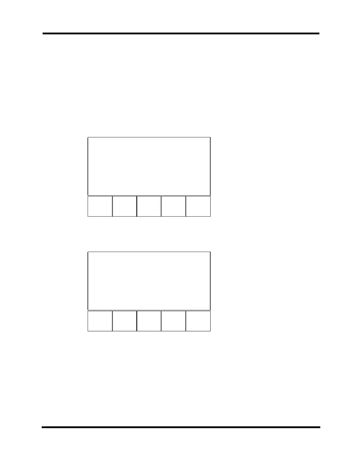
The Fault Masks page (Page 9) is used to setup the fault mask parameters. The Fault
Masks page is shown in Figure 3-21. This page differs from the other Setup pages, as it is
the only page that requires another page to change parameter values. The user need not
enter the hexadecimal numbers in any fault mask. As shown in the figures, the page
instructs the user to press ENTER to expand the mask. The expanded Fault Masks page
breaks down the selected fault mask into its individual bits so the user can edit them one
at a time. An example of an expanded Fault Masks page is shown in Figure 3-22.
F1 F2 F3 F4
Fault Masks
Page 9 Axis 1,
61
AUX output FFFFFFF00
0
Halt queue FFFFFFF00
0
Abort motion FFFFFFFF7
F
Enable brake FFFFFFF00
0
Press ENTER to expand mask!
Back Next Axis Default
it
Figure 3-21. Fault Masks Page
The functions at the bottom of the page are the same as for any axis parameter.
F1 F2 F3 F4
Global fault masks
Page 9 Axis 1, 1
Position error 0
RMS current error 0
Integral error 0
CW Hardware 1
k
Figure 3-22. Expanded Fault Masks Page
The complete fault mask spans several pages. Use the up and down arrow keys to scroll
through the list of faults. The Back key (F5) returns the user to the original Fault Masks
page. To toggle between a 0 and a 1, press the left and right arrow keys.
Artisan Technology Group - Quality Instrumentation ... Guaranteed | (888) 88-SOURCE | www.artisantg.com


 To Next Page