How to Modulate a Signal Tunable Lasers
Agilent 8163A/B, 8164A/B, and 8166A/B User’s Guide, Fourth Edition 137
To enable wavelength locking:
1 Move to the Tunable Laser channel and press [Details].
2 Move to <Mod Src> and press Enter.
3 Move to <Wavel. Locking>, by using the cursor key, and press Enter.
The text λLock appears in the Tunable Laser channel.
External Digital Modulation using Input Trigger
Connector
External digital modulation uses a TTL-level signal. Apply this signal
to the Input Trigger connector on the rear panel of your mainframe.
For information on external digital modulation, see “External Digital
Modulation” on page 134.
CAUTION A maximum of 5 V can be applied as an external voltage to the Input
Trigger connector, see page 290.
Take care not to use the Trigger Output connector or the Remote
Interlock connector for modulation. Do not apply an external voltage
to these connectors.
NOTE If external digital modulation using the Input Trigger Connector,
<Backplane>, is chosen as the modulation source, [Mod Src], the
Agilent 81689A Tunable Laser module behaves differently from all
other modules. If the duty cycle varies:
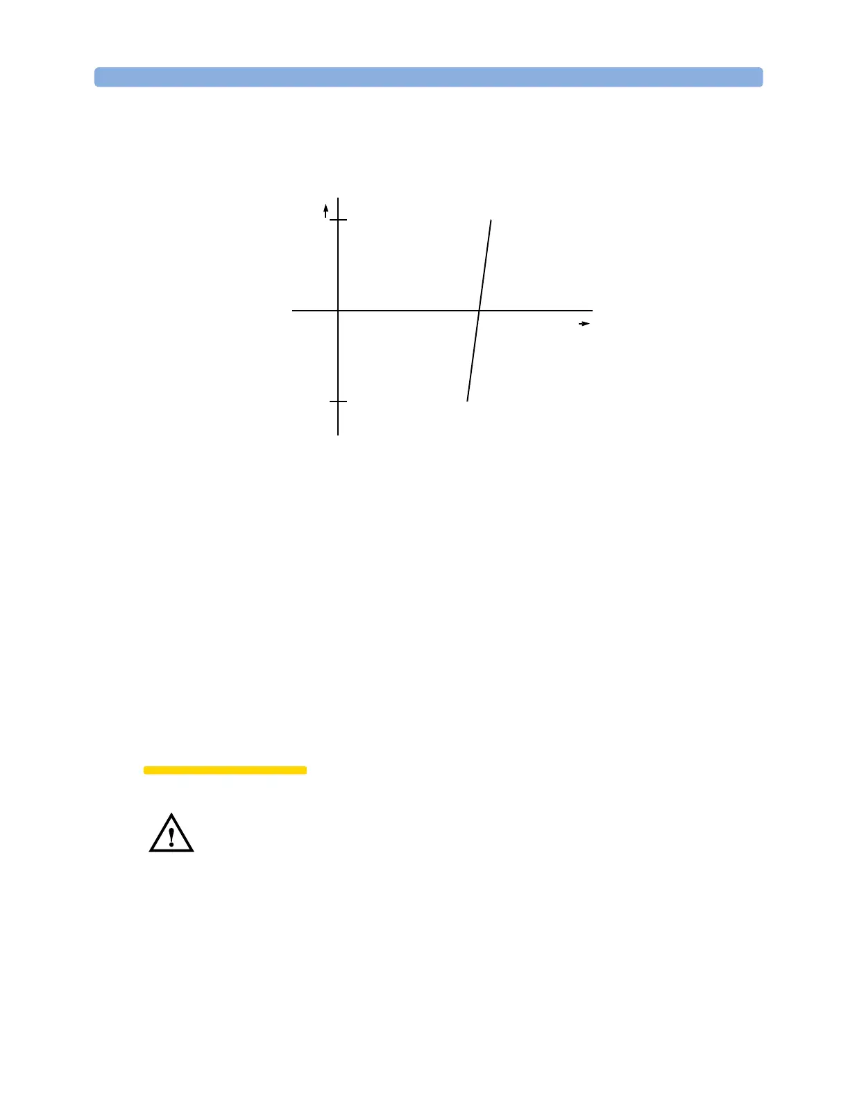
Figure 78 Wavelength Locking
λ
V
+5 V
-5 V
 Loading...


