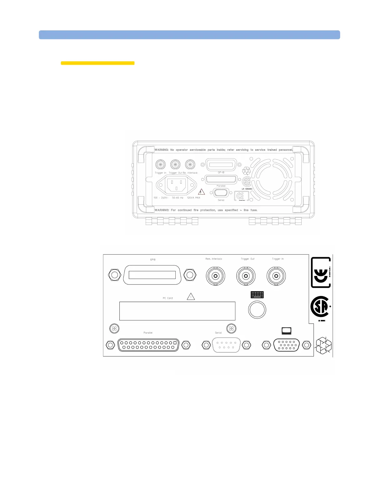
Installation and Maintenance Input and Output Connectors
290 Agilent 8163A/B, 8164A/B, and 8166A/B User’s Guide, Fourth Edition
CAUTION There are two input BNC connectors: the Remote Interlock Connector
and the Trigger Input, see Figure 195 or Figure 196. These are TTL
inputs. A maximum of 5 V can be applied as an external voltage to
either of these input connectors.
There is one output BNC connector: the Trigger Output, see Figure 195
or Figure 196. This is a TTL output. Do not apply an external voltage to
this connector.
Figure 195 Rear Panel of the Agilent 8163B Lightwave Multimeter System
Figure 196 Rear Panel of the Agilent 8164B Lightwave Measurement System
 Loading...


