Setting Attenuation and/or Power Levels How to Use a Variable Optical Attenuator module
192 Agilent 8163A/B, 8164A/B, and 8166A/B User’s Guide, Fourth Edition
For a multi-wavelength DWDM signal, your determined effective
wavelength λ
effective
is valid until there is some change to the signal’s
optical power vs wavelength spectrum.
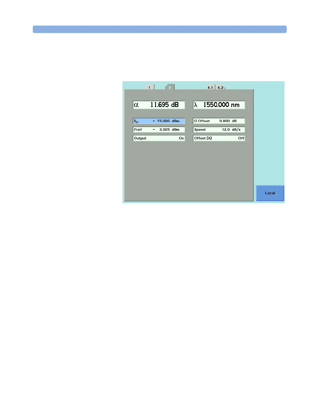
Figure 121 81560A/61A Calibration using Pref
Figure 121 shows an 81560A or 81561A Attenuator module calibrated
against a P
ref
of -3.305 dBm. P
SET
is -15.000 dBm. The Attenuation α
applied reflects P
ref
such that P
SET
is the power level at the DUT input.
Calibrating Test Setups that use an
81566A/67A/76A/77A Attenuator module
Requirement for Calibration 81566A/67A/76A/77A Attenuator modules with Power Control
incorporate a powermeter that allows you to control the output power
level of the module. After calibration for the losses in the patchcords
and connectors between this output and the DUT input, you can set
absolute power levels at the DUT input.
Furthermore, when the Attenuator’s Power Control feature is enabled,
the Attenuator module automatically corrects for power changes at its
input to maintain your desired output power.
Preconditions • To make the calibration as quick and simple as possible, host your
reference powermeter in the same mainframe as the Attenuator
module, as described in “Hosting a Reference Powermeter” on
page 183.
 Loading...


