How to Use an Optical Switch module Switching Optical Routes
Agilent 8163A/B, 8164A/B, and 8166A/B User’s Guide, Fourth Edition 207
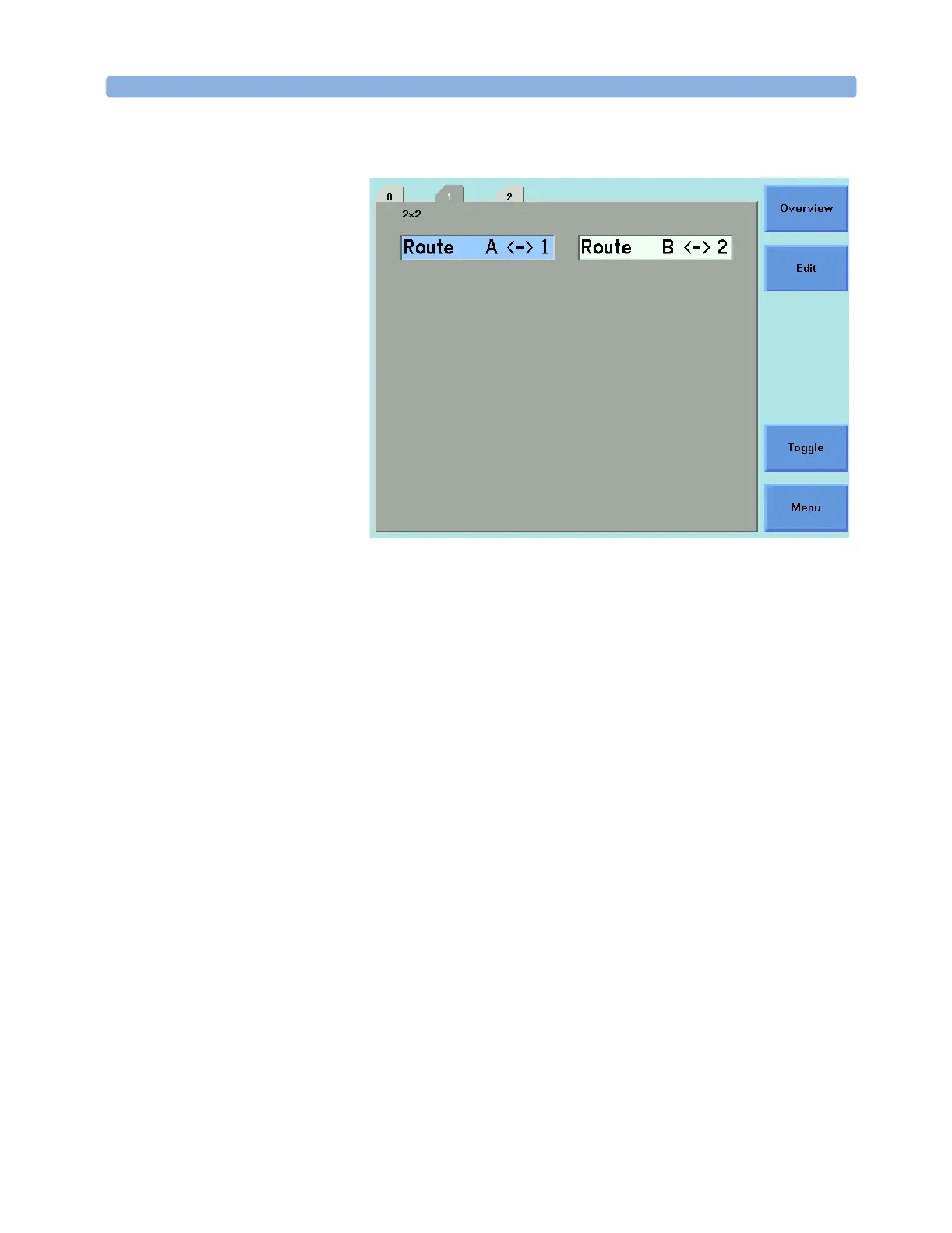
Figure 129 Optical Switch module, 8164A/B User Interface Details
Screen Elements All the figures in this chapter are taken from an 8164A/B mainframe.
The user interface for an 8163A, 8163B, 8166A or 8163B mainframe
may differ in detail but the available functionality is identical.
Configuration The Optical Switch configuration is indicated at the top left of the user
interface.
In Figure 129, 2x2 indicates that this is an Agilent 81594A/S 2x2 non-
blocking (crossover) switch.
Route The [Route A <->] field describes the route between port A and another
numbered port within the Optical Switch module.
If present, the [Route B <->] field describes the route between port B
and another numbered port within the Optical Switch module.
In Figure 129:
–The [Route A <->] field shows that, within the Optical Switch
module, port A is connected to port 1.
–The [Route B <->] field shows that, within the Optical Switch
module, port B is connected to port 2.
NOTE
For all switch modules the signal paths are bi-directional.
 Loading...


